
Bridge/Router Installation Guide

3-5
Cisco CRS-1 Carrier Routing System 4-Slot Line Card Chassis Installation Guide
OL-10971-07
Chapter 3 Installing and Removing Air Circulation Components
How to Install or Remove Air Circulation Components
Required Tools and Equipment
You need the following tools and part to perform this task:
• ESD-preventive wrist strap
• Large flat-blade screwdriver
• Fan tray (Cisco product number CRS-4-FAN-TR=)
Steps
To install a fan tray, follow these steps:
Step 1 Attach the ESD-preventive wrist strap to your wrist and connect its leash to one of the ESD connection
sockets on the rear (SFC) side of the chassis or a bare metal surface on the chassis.
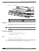
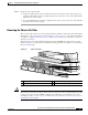
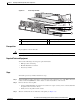
Step 2 Holding the fan tray by the handles, position it in front of the fan tray bay on the upper rear (SFC) side
of the chassis. Slide the tray partway into its slot.
Caution A fan tray weighs approximately 16 lb (7 kg.). Use two hands when handling a fan tray.
Caution Do not set the fan tray down on the connector; doing so could damage it.
Step 3 Slide the fan tray all the way in. Press it firmly into the chassis so that the connector on the back of the
fan tray is seated firmly against the connector on the interior of the chassis.
Caution To prevent damage to the chassis connector, do not use excessive force when inserting a fan
tray into its bay.
Step 4 Using the screwdriver, tighten the four captive screws (one for each corner).
Note All electrical and control line connections are made automatically when the connectors mate.
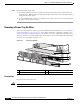
Removing a Fan Tray
This section describes how to remove a fan tray from the Cisco CRS-1 4-slot line card chassis. For
information on the chassis airflow and circulation, see the
“About Line Card Chassis Airflow” section
on page 3-1.
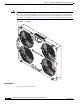
The fan tray installs into the rear (SFC) side of the chassis (see Figure 3-4). For complete information
on regulatory compliance and safety, see Cisco CRS-1 Carrier Routing System Regulatory Compliance
and Safety Information.