
Bridge/Router Installation Guide

2-22
Cisco CRS-1 Carrier Routing System 4-Slot Line Card Chassis Installation Guide
OL-10971-07
Chapter 2 Installing and Removing Power Components
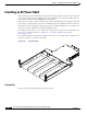
Installing an AC Power Shelf
Installing an AC Power Shelf
This section describes how to install an AC power shelf in the Cisco CRS-1 4-slot line card chassis. The
power shelf encloses four power supplies and the power distribution connections and wiring. The AC
power shelf is installed in the front (PLIM) side of the chassis.
The AC-powered chassis contains a single AC power shelf containing four AC power supplies. Each AC
power supply converts input AC power to the -54 VDC used by the Cisco CRS-1 4-slot line card chassis.
The AC power shelf is configured for single-phase AC power supply wiring(two wires + ground), and is
safety-rated at 110 to 240V VAC nominal, 50 to 60 Hz (4x) 11A.
For additional power details, see Cisco CRS-1 Carrier Routing System 4-Slot Line Card Chassis System
Description, or in this document, see
Appendix A, “Cisco CRS-1 4-Slot Line Card Chassis
System Specifications.”
For complete information on regulatory compliance and safety, see Cisco CRS-1 Carrier Routing System
Regulatory Compliance and Safety Information.
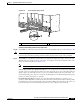
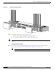
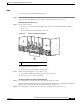
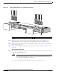
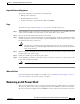
Figure 2-18 AC Power Shelf
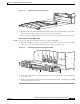
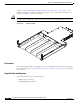
Prerequisites
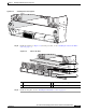
Remove the air intake grille from the bottom of the chassis.
158348