
Bridge/Router Installation Guide

2-21
Cisco CRS-1 Carrier Routing System 4-Slot Line Card Chassis Installation Guide
OL-10971-07
Chapter 2 Installing and Removing Power Components
Removing a DC Power Shelf
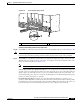
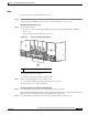
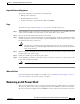
Figure 2-16 Removing the DC Power Input Shelf
b. Holding the DC power input shelf underneath with one hand and steadying it with the other, lift the
DC power input shelf up and slide it part way out of the power shelf slot.
c. Slide the DC power input shelf fully out of the chassis. Set the power input shelf carefully aside.
Remove the DC Power Input Module (PIM)
Step 10 Go to the rear of the chassis. Remove the DC power input module (PIM).
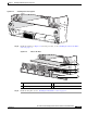
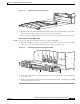
a. With a No. 2 Phillips screwdriver, remove the first set of eight screws—six screws in the front of the
chassis, two on the outside right and left sides of the chassis (see
Figure 2-17).
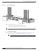
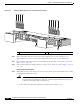
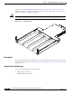
Figure 2-17 Removing the DC Power Input Module (PIM)
b. Remove the additional two screws underneath the chassis (one on the left side, one on the right side)
(see
Figure 2-17).
c. With one hand gripping the handle and one hand underneath the module, carefully remove the PIM
from the chassis; then set it aside.
STA
TUS
STA
TUS
STA
TUS
STA
TUS
210862
S
T
A
T
U
S
S
T
A
T
U
S
S
T
A
T
U
S
S
T
A
T
U
S
210622
B1
(R
T
N
)
(-4
8
V
/-60V
)
+
–
B0
B0
B1
ON
Side B
(R
T
N
)
(-4
8
V/-6
0V
)
+
–
A1
(R
TN)(-4
8
V
/-6
0
V
)
+
–
A0
(R
T
N
)
(-48
V
/-6
0V
)
+
–
A0A1
ON
Side A
SIDE A
SIDE B