
Bridge/Router Installation Guide

2-20
Cisco CRS-1 Carrier Routing System 4-Slot Line Card Chassis Installation Guide
OL-10971-07
Chapter 2 Installing and Removing Power Components
Removing a DC Power Shelf
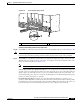
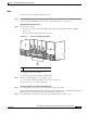
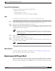
Figure 2-15 Removing Wiring Block Covers and DC Input Power Cables
Step 6 With a 5 mm Allen wrench, loosen the power shelf coupling screw (see item 2 in Figure 2-15).
This will allow you to remove the DC power input shelf from the chassis (as described below).
Step 7 Go to the front of the chassis. Remove the inlet grille. For the procedure, see the “Removing the Inlet
Grille” section on page 5-3.
Step 8 Remove the four DC power supplies. For the procedure, see the “Removing a Power Supply” section on
page 2-28.
Remove the DC Power Input Shelf
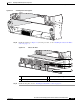
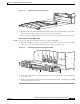
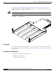
Step 9 While still in the front of the chassis, you can now remove the DC power input shelf. To remove the DC
power input shelf, follow these steps:
Caution An empty DC power input shelf weighs approximately 15.5 lb (7 kg).
To prevent injury when lifting the shelf, keep your back straight and lift with your legs, not
your back. Avoid sudden twists or lateral moves.
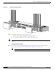
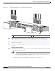
a. To unlock the power input shelf, pull the lever handles down (see Figure 2-16).
1 Power shelf coupling screw 2 Grounding lug nuts
210863
B
1
(RTN
)
(-48V/-60V)
+
–
B
0
B
0B
1
O
N
Side B
(RTN) (-48V/-60V)
+
–
A1
(RTN) (-48V/-60V)
+
–
A
0
(RTN) (-48V/-60V)
+
–
A
0
A
1
O
N
Side A
S
ID
E
A
S
IDE
B
2
1