
Bridge/Router Installation Guide

2-16
Cisco CRS-1 Carrier Routing System 4-Slot Line Card Chassis Installation Guide
OL-10971-07
Chapter 2 Installing and Removing Power Components
Installing a DC Power Shelf
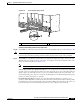
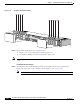
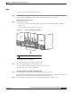
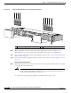
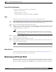
Figure 2-11 DC Power Shelf Cable Cabling
Step 12 Reattach both wiring block covers (see Figure 2-11).
a. Snap the cover over the wiring block so that it snaps closed.
b. Use a number 1 Phillips screwdriver to tighten the capture screw.
Note The wiring block covers can be oriented to route the wire cabling from the top or the bottom of the
covers.
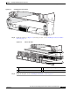
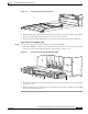
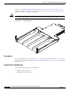
Installing the DC Power Supplies
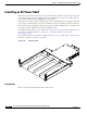
Step 13 Go to the front of the chassis. Install the four DC power supplies into the power input shelf (see
Figure 2-12). For details, see the “Installing a Power Supply” section on page 2-25.
Note Each DC power supply weighs 4.5 lb (2 kg).
210613
B
1
(RTN
)
(-48V/-60V)
+
–
B
0
B
0B
1
O
N
Side B
(RTN) (-48V/-60V)
+
–
A
1
(RTN) (-48V/-60V)
+
–
A
0
(RTN) (-48V/-60V)
+
–
A
0
A
1
O
N
Side A
S
ID
E
A
S
IDE
B