
Bridge/Router Installation Guide


2-13
Cisco CRS-1 Carrier Routing System 4-Slot Line Card Chassis Installation Guide
OL-10971-07
Chapter 2 Installing and Removing Power Components
Installing a DC Power Shelf
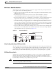
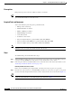
Figure 2-7 Removing the Rear Power Access Panels
Step 4 Unscrew the coupling screw from each panel with a medium flat-blade screwdriver. Set aside the access
panels and their screws.
Note You will need these screws later when you install the power input module (PIM).
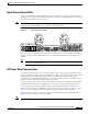
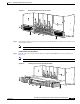
Installing the DC Power Input Module
Step 5 From the rear of the chassis, insert the DC power input module (PIM) into the open power bay (see
Figure 2-8).
Note The PIM weighs 6.5 lb (2.9 kg).
Figure 2-8 Inserting the DC Power Input Module (PIM)
S
T
A
T
U
S
S
T
A
T
U
S
S
T
A
T
U
S
S
T
A
T
U
S
210619
S
ID
E
A
S
T
A
T
U
S
S
T
A
T
U
S
S
T
A
T
U
S
S
T
A
T
U
S
210622
B1
(R
T
N
)
(-4
8
V
/-60
V
)
+
–
B0
B0
B1
ON
Side B
(R
T
N
)
(-4
8
V/-6
0
V
)
+
–
A1
(R
TN)(-4
8
V
/-6
0V
)
+
–
A0
(R
T
N
)
(-4
8
V
/-6
0V
)
+
–
A0A1
ON
Side A
SIDE A
SIDE B