
Bridge/Router Installation Guide


2-12
Cisco CRS-1 Carrier Routing System 4-Slot Line Card Chassis Installation Guide
OL-10971-07
Chapter 2 Installing and Removing Power Components
Installing a DC Power Shelf
Prerequisites
Bring down the power to the Cisco CRS-1 4-slot line card chassis.
Tip We recommend that you do this procedure with the line card chassis mounted in a rack with sufficient
space for bottom and side access to the screws.
Required Tools and Equipment
You need the following tools and parts to perform this task:
• ESD-preventive wrist strap
• Medium flat-blade screwdriver
• Number 1 Phillips screwdriver
• Medium Phillips screwdriver
• 5 mm Allen wrench
• 10 mm hex socket wrench
• DC power input shelf (Cisco product number: CRS-4-DC-INPUT)
• DC power input module (PIM) (Cisco product number: CRS-4-DC-PIM)
• DC power supplies (Cisco product number: CRS-4-DC-SUPPLY)
Note This procedure assumes that the Cisco CRS-1 4-slot line card chassis is already mounted in a rack with
sufficient room to access the sides and the bottom of the chassis.
Steps
To install the DC power shelf, follow these steps:
Step 1 Attach the ESD-preventive wrist strap to your wrist and connect its leash to one of the ESD connection
sockets on the front (PLIM) side of the chassis or a bare metal surface on the chassis.
Step 2 If the AC power shelf is currently installed, remove it from the front of the chassis. (For details, see the
“Removing an AC Power Shelf” section on page 2-23.)
Removing the Rear Power Access Panels
Before you can install the power input module, you must remove the rear power access panels.
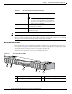
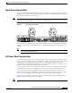
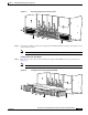
Step 3 From the rear of the chassis, use a medium Phillips screwdriver to remove the rear power access panels
(located on the bottom right and bottom left rear of the chassis). Remove the screws shown in
Figure 2-7.
Tip One screw on each side is located under the chassis (as indicated in Figure 2-7). To access this screw
safely, the chassis must be in a rack with adequate space below the chassis.