
Bridge/Router Installation Guide


2-5
Cisco CRS-1 Carrier Routing System 4-Slot Line Card Chassis Installation Guide
OL-10971-07
Chapter 2 Installing and Removing Power Components
DC Power Systems on the Cisco CRS-1 4-Slot Router
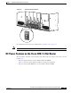
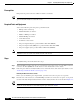
Figure 2-2 AC Power Enable Switches
For an illustration of the DC power enable switches, see Figure 2-14 on page 2-19.
Note All power cords must be unplugged from wall power to fully remove power from the chassis.
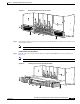
DC Power Systems on the Cisco CRS-1 4-Slot Router
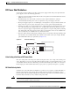
The Cisco CRS-1 4-slot line card chassis DC power shelf consists of two major components, as shown
in
Figure 2-3:
• DC power input shelf (Cisco product number: CRS-4-DC-INPUT)
Figure 2-3 shows the power supplies installed in the DC power input shelf.
• DC power input module (PIM) (Cisco product number: CRS-4-DC-PIM)
S
T
A
T
U
S
S
T
A
T
U
S
S
T
A
T
U
S
S
T
A
T
U
S
158455