
Bridge/Router Installation Guide


2-3
Cisco CRS-1 Carrier Routing System 4-Slot Line Card Chassis Installation Guide
OL-10971-07
Chapter 2 Installing and Removing Power Components
About Installing and Removing the Power Components
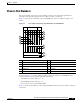
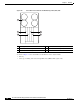
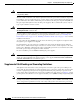
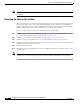
Figure 2-1 NEBS Bonding and Grounding Points (Rear of Chassis)
If you plan to connect the Cisco CRS-1 4-slot line card chassis system to a network equipment building
system (NEBS)-compliant supplemental bonding and grounding system at the site, you must have the
following:
• A minimum of one ground lug that has two M6 bolt holes with 0.625-inch (15.86-mm) spacing
between them, and a wire receptacle large enough to accept a 6-AWG or larger multistrand copper
wire. The lug is similar to the type used for the DC-input power supply leads. This ground lug is not
available from Cisco Systems. This type of lug is available from electrical-connector vendors, such
as Panduit.
• Two M6 nuts with locking washers (nickel-plated brass is ideal). This hardware is not available from
Cisco Systems; they are available from any commercial hardware vendor.
• A commensurately rated ground wire. The actual wire diameter and length depend on your router
location and site environment. This wire is not available from Cisco Systems; it is available from
any commercial cable vendor.
1 NEBS bonding and grounding stud
S
T
A
T
U
S
S
T
A
T
U
S
S
T
A
T
U
S
S
T
A
T
U
S
158392
1