
Bridge/Router Installation Guide


CHAPTER
2-1
Cisco CRS-1 Carrier Routing System 4-Slot Line Card Chassis Installation Guide
OL-10971-07
2
Installing and Removing Power Components
This chapter provides instructions on how to install and remove the Cisco CRS-1 Carrier Routing System
4-Slot Line Card Chassis power components.
This chapter presents the following topics:
• About Installing and Removing the Power Components
• DC Power Systems on the Cisco CRS-1 4-Slot Router
• Installing a DC Power Shelf
• Removing a DC Power Shelf
• Installing an AC Power Shelf
• Removing an AC Power Shelf
• Installing a Power Supply
• Removing a Power Supply
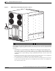
About Installing and Removing the Power Components
This section contains some general information about the power components.
• Basic Chassis Power Recommendations
• Supplemental Unit Bonding and Grounding Guidelines
• Powering the Chassis Up or Down
Basic Chassis Power Recommendations
The Cisco CRS-1 Carrier Routing System 4-Slot Line Card Chassis can be configured with either an
AC-input power subsystem or a DC-input power subsystem. Site power requirements differ depending
on the source voltage used. Follow these precautions and recommendations when planning power
connections to the router:
• Check the power at your site before installation and periodically after installation to ensure that you
are receiving clean power. Install a power conditioner, if necessary.
• Install proper grounding to avoid damage from lightning and power surges.