
Bridge/Router Installation Guide


1-10
Cisco CRS-1 Carrier Routing System 4-Slot Line Card Chassis Installation Guide
OL-10971-07
Chapter 1 Overview
Recommended Chassis Installation Task Sequence
Recommended Chassis Installation Task Sequence
This section provides the recommended task sequence for installing a new Cisco CRS-1 4-slot line card
chassis.
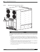
Step 1 If your system was shipped with AC power, remove the four AC power cords from the box, and do the
following:
a. Insert all four power cords into the AC power source.
b. Insert the power cords into the AC power plugs at the base of the rear of the chassis.
Step 2 Turn the power enable switches (for your AC or DC power system) to the ON position. For details, see
the
“Powering the Chassis Up or Down” section on page 2-4.
All power should come up properly. The LEDs above the enable switches should be lit green. The fans
in the front of the chassis should start operating.
Step 3 Install the switch fabric cards (SFCs). For the procedure, see the “How to Install or Remove a Switch
Fabric Card” section on page 4-18.
Step 4 Install the route processors (RPs). For the procedure, see the “How to Install or Remove a Route
Processor Card” section on page 4-25.
Step 5 Install the modular service cards (MSCs). For the procedure, see the “How to Install or Remove a
Modular Services Card” section on page 4-33.
Step 6 Install the physical layer interface modules (PLIMs). For the procedure, see the “How to Install or
Remove a Physical Layer Interface Module” section on page 4-41.
Step 7 If the system was shipped with the grille and doors, install the inlet grille. See the “Installing the Inlet
Grille” section on page 5-2.
Step 8 Install the doors. See the “Installing the Doors” section on page 5-4.