
Bridge/Router Installation Guide


1-3
Cisco CRS-1 Carrier Routing System 4-Slot Line Card Chassis Installation Guide
OL-10971-07
Chapter 1 Overview
Chassis Components
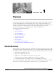
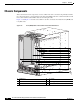
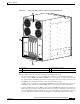
Figure 1-2 Rear (SFC) View of the Cisco CRS-1 4-Slot Line Card Chassis
The Cisco CRS-1 4-slot line card chassis contains the following components:
• As many as four modular services cards (MSCs, also called line cards) and four physical layer
interface modules (PLIMs). The MSC and PLIM are an associated pair of cards that mate through
the chassis midplane. The MSC provides the forwarding engine for Layer 3 routing of user data, and
the PLIM provides the physical interface and connectors for the user data.
An MSC can be associated with several different PLIMs that provide different interface speeds and
technologies. For a full list of available PLIMs, please contact your Cisco sales representative.
• A chassis midplane that connects MSCs to their associated PLIMs. The midplane design allows an
MSC to be removed from the chassis without having to disconnect the cables that are attached to the
associated PLIM. The midplane distributes power, connects the MSCs to the switch fabric cards, and
provides control plane interconnections. The midplane is not field replaceable by the customer.
1 Fan tray 3 Switch fabric card slots
2 AC power plug connectors
S
T
A
T
U
S
S
T
A
T
U
S
ST
A
T
U
S
ST
A
T
U
S
158296
3
1
2