
Bridge/Router Installation Guide


Index
IN-2
Cisco CRS-1 Carrier Routing System 4-Slot Line Card Chassis Installation Guide
OL-10971-07
CRS-1 routing system
air filter 1-7
airflow and exhaust 1-8
chassis installation task sequence 1-10
chassis slot numbers 1-5
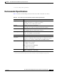
environmental specifications A-3
line card chassis specifications A-1
power system recommendations 2-1
D
DC power
lug torque ranges A-2
DC power input module 2-5, 2-11
Cisco product number 2-5
coupling screw (figure) 2-15
figure 2-13
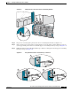
installing 2-13
mating to DC power input shelf 2-14
removing 2-21
weight of 2-13
wiring block 2-8
wiring block covers, cabling orientation 2-16
DC power input shelf
Cisco product number 2-5
figure 2-14
installing 2-14
mating to PIM 2-14
removing 2-20, 2-21
weight of 2-14
DC power shelf
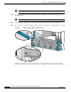
cable wiring (figure) 2-16
components 2-5
coupling screw 2-15
DC input current and voltage 2-8
earth conductor gauge 2-9
enable switches 2-19
ground wire torque value 2-15
guidelines 2-7
installing 2-11
power input module (PIM) 2-5
removing 2-18
torque value for DC input power cables 2-15
torque value for ground wire 2-15
wiring 2-15
wiring block covers 2-16
DC power systems
cable lug (figure) 2-7
color coding of DC power cable 2-7, 2-15
converting from AC power 2-11
DC power input shelf 2-14
DC power shelf guidelines 2-7
input current and voltage 2-8
input-power-present LEDs 2-9
polarity, verifying 2-7, 2-15
power cables, recommendations 2-7
power supplies 2-16
reverse polarity, if detected 2-7
wire characteristics 2-9
doors
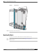
installing 5-4
knob latch 5-5
latch button 5-6
lower door mounting bracket 5-5
opening 5-7
removing 5-8
E
earth conductor guage 2-9
ejector levers
and captive screws (figure) 4-2
operating (figure) 4-3
electrostatic discharge, preventing 1-9
enable switches
AC power shelf 2-5
DC power shelf 2-19