
Bridge/Router Installation Guide


IN-1
Cisco CRS-1 Carrier Routing System 4-Slot Line Card Chassis Installation Guide
OL-10971-07
INDEX
A
acoustic noise specification, system A-3
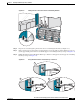
AC power shelf
converting to DC power 2-11
enable switches (figure) 2-5
figure 2-22
installing 2-22
removing 2-23
weight of 2-25
air circulation components
installing 3-1
removing 3-3
air filter 1-7, 3-2
figure 2-17, 3-8, 3-9
installing 3-7
removing 3-9
replacement frequency recommendation 3-2
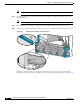
air filter (power tray)
figure 3-11, 3-12
installing 3-10
removing 3-12
airflow 3-1
(figure) 1-8, 3-2, 3-3
altitude specifications, system A-3
B
bale-clasp SFP
installing 4-53
removing 4-54
bonding
(figure) 2-3
guidelines 2-2
C
cable management bracket 1-7
(figure) 1-7
figure 4-5
information about 4-4
card
handle 4-11
handle (figure) 4-12
installation and removal, guidelines for 4-2
online insertion and removal (OIR) 4-2
slide-assistance arm 4-11
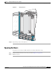
chassis
air circulation components 3-1
air filter (figure) 2-17, 3-8, 3-9
airflow 3-1
airflow (figure) 1-8, 3-2, 3-3
components 1-2
cooling system 1-7, 3-1
front view (figure) 1-2
grounding (figure) 2-3
installation task sequence 1-10
midplane, description 1-3
overview 1-1
rear view (figure) 1-3
slot numbers 1-5
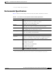
specifications A-1
components, CRS-1 routing system 1-2
cooling system, chassis 1-7, 3-1