
Bridge/Router Installation Guide


A-2
Cisco CRS-1 Carrier Routing System 4-Slot Line Card Chassis Installation Guide
OL-10971-07
Appendix A Cisco CRS-1 4-Slot Line Card Chassis System Specifications
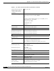
Cisco CRS-1 4-Slot Line Card Chassis Specifications
Chassis with all components
installed (without exterior
cosmetic components and
packaging)
361 lb (163.7 kg)
Cards and Modules Supported
4 modular services cards (MSCs)
4 physical layer interface modules (PLIMs)
or
4 shared port adapter (SPA) interface processors (SIPs), each of
which supports one or more SPAs
2 route processors (RPs)
4 switch fabric cards
1 fan tray
Power Shelves
AC power shelf Supports four AC-to-DC rectifiers
DC power shelf Supports four DC power supplies
Maximum Power Consumption Total input power
Maximum AC input power 4185 W (assuming 92% efficiency)
Maximum DC input power 4278 W (assuming 90% efficiency)
DC power lug torque ranges
Minimum torque 20 in-lb (2.2 N-m)
Maximum torque 30 in-lb (3.3 N-m)
Power Redundancy
AC 1:1—Requires two independent AC sources
DC We recommend two independent -48 VDC power sources
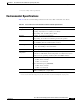
AC Input Power
2W+PE (2 wire + protective earthing
1
)
Nominal input voltage 200 to 240 VAC
(range: 180 to 264 VAC)
Nominal line frequency 50 or 60 Hz
(range: 47 to 63 Hz)
Recommended AC service 20 A (per AC rectifier)
DC Input Power
Nominal input voltage Supports -48 VDC and -60 VDC systems (range: –40 to –72 VDC)
Input line current 50-A maximum at –48 VDC
40-A maximum at –60 VDC
Inrush current 60-A peak at 75 VDC
(maximum for 1 ms)
Chassis Cooling
1 fan tray, pull configuration
Chassis airflow Up to 880 cubic ft (24,919 liters) per minute
Power shelf airflow 60 cubic ft (1699 liters) per minute
Table A-1 Cisco CRS-1 4-Slot Line Card Chassis Specifications (continued)