
Bridge/Router Installation Guide


5-4
Cisco CRS-1 Carrier Routing System 4-Slot Line Card Chassis Installation Guide
OL-10971-07
Chapter 5 Installing and Removing the Doors and Grille
Installing the Doors
Steps
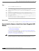
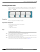
To remove the inlet grille, follow these steps:
Step 1 Attach the ESD-preventive wrist strap to your wrist and connect its leash to an ESD connection socket
on the front side or a bare metal surface on the chassis.
Step 2 If the doors have been installed, open the doors to get complete access to the grille.
Step 3 Using the Number 2 flat-blade screwdriver, unscrew the two captured screws at the upper right and left
corners of the grille.
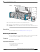
Step 4 Firmly grasp the outside edges of the inlet grille.
Step 5 Pull the bottom of the grille firmly away from the chassis; it loosens from the connecting ball studs.
Step 6 Carefully set the inlet grille aside.
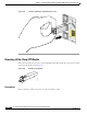
Installing the Doors
This section describes how to install the doors on the Cisco CRS-1 4-slot chassis. We recommend that
you install the doors when the chassis has been mounted into its rack.
Prerequisites
Before you install the doors on the Cisco CRS-1 4-slot chassis, you must install the grille as described
above.
Required Tools and Equipment
You need the following tool and parts to perform this task:
• ESD-preventive wrist strap
• Left and right doors (Cisco product number: CRS-4-DOOR-KIT)
Steps
To install the doors on the Cisco CRS-1 4-slot chassis, follow these steps:
Step 1 Remove the door from its packaging (including the protective film that covers each door), and set the
packaging aside.
Step 2 Attach the ESD-preventive wrist strap to your wrist; then connect its leash to an ESD connection socket
or a bare metal surface on the chassis.
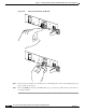
Step 3 Starting with the left door, align the bottom guide pin over the hole in the lower door mounting bracket
(see
Figure 5-3).