
Bridge/Router Installation Guide


5-2
Cisco CRS-1 Carrier Routing System 4-Slot Line Card Chassis Installation Guide
OL-10971-07
Chapter 5 Installing and Removing the Doors and Grille
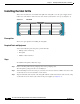
Installing the Inlet Grille
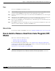
Installing the Inlet Grille
This section describes how to install the inlet grille. The inlet grille covers the power supply and air
intake areas at the bottom of the front side of the chassis, just below the card cage (see Figure 5-1).
Figure 5-1 Inlet Grille
Prerequisites
There are no prerequisites for installing the inlet grille.
Required Tools and Equipment
You need the following tools and part to perform this task:
• ESD-preventive wrist strap
• Inlet grille
• Number 2 flat screwdriver
Steps
To install the inlet grille, follow these steps:
Step 1 Remove the inlet grille from its packaging, then set the packaging aside.
The inlet grille is packaged in the door assembly box.
Step 2 Attach the ESD-preventive wrist strap to your wrist and connect its leash to an ESD connection socket
on the front side or a bare metal surface on the chassis.
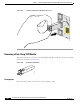
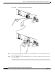
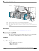
Step 3 Align the ball studs at the bottom of the inlet grille with the cutouts at the bottom of the chassis casing
on the front side of the chassis, just in front of the power supplies (see
Figure 5-2).
210174