
Bridge/Router Installation Guide

4-49
Cisco CRS-1 Carrier Routing System 4-Slot Line Card Chassis Installation Guide
OL-10971-07
Chapter 4 Installing and Removing SFCs, RPs, MSCs, PLIMs, and Associated Components
How to Install or Remove a Physical Layer Interface Module
Step 1 Attach the ESD-preventive wrist strap to your wrist and connect its leash to one of the ESD connection
sockets on the front (PLIM) side of the chassis or a bare metal surface on the chassis.
Step 2 Identify the card to be replaced.
Step 3 Loosen the two captive screws holding the card in place.
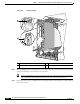
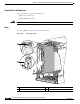
Step 4 Grasp the two card ejector levers and simultaneously pivot both ejector levers 90 degrees (70 degrees for
a newer PLIM) away from the front edge of the card carrier to unseat the card from the backplane
connector.
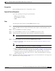
Step 5 Grasp the slide-assistance arm (if installed) or the card carrier edges, and gently pull the PLIM halfway
from the slot.
Step 6 Move one hand under the PLIM to guide it. Avoid touching the PLIM printed circuit board, components,
or any connector pins. Do not lift cards by the slide-assistance arm; lift them from the bottom, using the
slide-assistance arm only as an aid for balance.
Step 7 Slide the card from the slot and place it directly into an antistatic sack or other ESD-preventive container.
Warning
Because invisible laser radiation may be emitted from the aperture of the port when no cable is
connected, avoid exposure to laser radiation and do not stare into open apertures.
Statement 70
Some PLIMs contain Class 1 lasers, and some contain Class 1M lasers. See the documentation for the
specific PLIM for details.
What to Do Next
After performing this task, replace any front cover plates.
Verifying the Installation of a PLIM
This section describes how to verify that the PLIM has been properly installed.
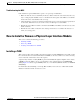
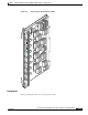
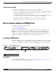
Figure 4-30 shows the PLIM front panel (in this case, a 16 x OC-48c/STM-16c
Packet-over-SONET/SDH [POS]).
Figure 4-30 PLIM Front Panel
Use the status LEDs, located on the PLIM faceplate, to verify the correct installation of the card:
There are two types of LEDs on a PLIM: the board-level LED labeled Status and the port-level LEDs
that are labeled differently depending on the PLIM type.
When the PLIM is properly installed, the Status LED turns green. If this LED is off, verify that the PLIM
is installed correctly. (For details on the information provided by the port-level LEDs, see the
documentation specific to that PLIM.)
111850