
Bridge/Router Installation Guide

4-44
Cisco CRS-1 Carrier Routing System 4-Slot Line Card Chassis Installation Guide
OL-10971-07
Chapter 4 Installing and Removing SFCs, RPs, MSCs, PLIMs, and Associated Components
How to Install or Remove a Physical Layer Interface Module
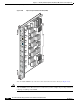
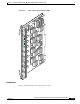
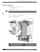
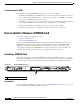
Figure 4-27 Installing a PLIM
Step 7 Orient the PLIM so that the status display is on top, then position the card for insertion into the card cage
slot. Avoid touching the card circuitry or any connectors.
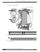
Note There are alignment grooves on each slot in the card cage. When you install a card, make sure
that you align both the top and bottom edges of the card carrier in the slot grooves.
Step 8 Grasp both card ejector levers simultaneously, then push them both outward until they are fully extended
in the open position.
1 Captive screw 3 Direction of installation or removal
2 Ejector lever
S
T
A
T
U
S
S
T
A
T
U
S
S
T
A
T
U
S
158461
3
1
2
S
T
A
T
U
S
S
T
A
T
U
S