
Bridge/Router Installation Guide


4-39
Cisco CRS-1 Carrier Routing System 4-Slot Line Card Chassis Installation Guide
OL-10971-07
Chapter 4 Installing and Removing SFCs, RPs, MSCs, PLIMs, and Associated Components
How to Install or Remove a Modular Services Card
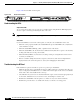
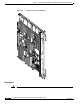
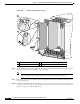
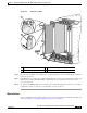
Figure 4-23 Removing an MSC
Step 6 Place the removed MSC on an antistatic mat, or immediately place it in an antistatic bag if you plan to
return it to the factory.
Step 7 If the MSC slot is to remain empty, install an MSC impedance carrier to keep dust from the chassis and
maintain proper airflow through the MSC compartment. See the
“Installing an Impedance Carrier”
section on page 4-10.
Step 8 To ensure proper EMI shielding and to maintain proper airflow throughout the chassis, use a screwdriver
to tighten the captive screws next to each impedance carrier ejector lever.
What to Do Next
If you are installing the Cisco CRS-1 4-slot line card chassis for the first time, install the inlet grille and
doors. (See
Chapter 5, “Installing and Removing the Doors and Grille.”)
1 Captive screw 3 Direction of installation or removal
2 Ejector lever
S
T
A
T
U
S
158363
S
T
A
T
U
S
S
T
A
T
U
S
3
S
T
A
T
U
S
1
2