
Bridge/Router Installation Guide


4-33
Cisco CRS-1 Carrier Routing System 4-Slot Line Card Chassis Installation Guide
OL-10971-07
Chapter 4 Installing and Removing SFCs, RPs, MSCs, PLIMs, and Associated Components
How to Install or Remove a Modular Services Card
How to Install or Remove a Modular Services Card
This section contains the following procedures:
• Installing an MSC
• Removing an MSC
• Verifying the Installation of an MSC
Installing an MSC
This section describes how to install a modular services card (MSC) in the Cisco CRS-1 4-slot line card
chassis. For more detailed information on the MSC, see Cisco CRS-1 Carrier Routing System 4-Slot Line
Card Chassis System Description.
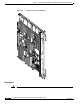
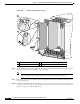
The MSC is a Layer 3 forwarding engine in the Cisco CRS-1 routing system (see Figure 4-21).
There are two versions of the MSC: the original version (CRS-MSC) and version B (CRS-MSC-B). Both
versions provide the same functionality.
An MSC can be paired with different types of physical layer interface modules (PLIMs) to provide a
variety of interfaces.
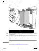
An MSC fits into any available MSC slot in the front of the chassis and connects directly to the midplane.
There are four MSC slots, with two on the left side (MSC slot
0 and MSC slot 1) and two on the right
side (MSC slot
2and MSC slot 3) (see Figure 4-17 on page 4-25).
Note If your Cisco CRS-1 4-slot line card chassis uses a Cisco CRS-1 SIP-800, refer to the “Installing and
Removing a SIP” chapter in the Cisco CRS-1 SIP and SPA Hardware Installation Guide on
www.cisco.com.