Cisco UCS C24 Server Installation and Service Guide Covers Server Generation M3 May 09, 2013 Americas Headquarters Cisco Systems, Inc. 170 West Tasman Drive San Jose, CA 95134-1706 USA http://www.cisco.
THE SPECIFICATIONS AND INFORMATION REGARDING THE PRODUCTS IN THIS MANUAL ARE SUBJECT TO CHANGE WITHOUT NOTICE. ALL STATEMENTS, INFORMATION, AND RECOMMENDATIONS IN THIS MANUAL ARE BELIEVED TO BE ACCURATE BUT ARE PRESENTED WITHOUT WARRANTY OF ANY KIND, EXPRESS OR IMPLIED. USERS MUST TAKE FULL RESPONSIBILITY FOR THEIR APPLICATION OF ANY PRODUCTS.
CONTENTS Preface v Related Documentation Organization Audience v v vi Documentation Feedback Conventions vi vi Obtaining Documentation and Submitting a Service Request CHAPTER 1 Overview CHAPTER 2 Installing the Server xi 1-1 2-1 Unpacking and Inspecting the Server 2-2 Preparing for Server Installation 2-3 Installation Guidelines 2-3 Rack Requirements 2-4 Equipment Requirements 2-4 Slide Rail Adjustment Range 2-4 Installing the Server In a Rack 2-5 Initial Server Setup 2-8 Connecting
Contents Cisco Integrated Management Interface (CIMC) Server Configuration Utility 3-1 Status LEDs and Buttons 3-2 Front Panel LEDs 3-2 Rear Panel LEDs and Buttons 3-1 3-4 Preparing for Server Component Installation 3-6 Required Equipment 3-6 Shutting Down and Powering Off the Server 3-6 Removing and Replacing the Server Top Cover 3-7 Removing and Replacing the Front Chassis Panel 3-8 Replaceable Component Locations 3-9 Serial Number Location 3-9 Color-Coded Touch Points 3-10 Installing or Replacing Ser
Contents Monitoring and Managing a Cisco USB Flash Drive 3-43 Internal Cisco USB Flash Drive Replacement Procedure 3-43 Enabling or Disabling the Internal USB Port 3-44 Installing a Trusted Platform Module 3-45 Enabling the Intel Trusted Execution Technology (TXT) Feature For the TPM Replacing a SCU Upgrade ROM Module 3-48 Replacing a Software RAID Key Module 3-49 Replacing Power Supplies 3-50 APPENDIX A Server Specifications 3-46 A-1 Physical Specifications A-1 Power Specifications A-2 450W Power
Contents Cisco UCS C24 Server RAID Cabling Instructions C-18 Backplane and Expander Options C-18 Small Form Factor 24-Drive Backplane With Expander Cabling C-18 Small Form Factor 16-Drive Backplane (No Expander) Cabling C-19 Large Form Factor 12-Drive Backplane With Expander Cabling C-20 Restoring RAID Configuration After Replacing a RAID Controller For More Information APPENDIX D C-21 C-21 Installation for Cisco UCS Integration D-1 Cisco UCS C24 Server Installation and Service Guide 4 OL-26647-01
Preface This preface describes the audience, organization, and conventions of the Cisco UCS C24 Server Installation and Service Guide. It also provides information about how to obtain related documentation.
Preface Audience This guide is for experienced network administrators who configure and maintain Cisco servers. Documentation Feedback To provide technical feedback on this document, or to report an error or omission, please send your comments to ucs-docfeedback@external.cisco.com. We appreciate your feedback. Conventions This document uses the following conventions for notes, cautions, and safety warnings. Notes and cautions contain important information that you should know.
Preface Varoitus TÄRKEITÄ TURVALLISUUSOHJEITA Tämä varoitusmerkki merkitsee vaaraa. Tilanne voi aiheuttaa ruumiillisia vammoja. Ennen kuin käsittelet laitteistoa, huomioi sähköpiirien käsittelemiseen liittyvät riskit ja tutustu onnettomuuksien yleisiin ehkäisytapoihin. Turvallisuusvaroitusten käännökset löytyvät laitteen mukana toimitettujen käännettyjen turvallisuusvaroitusten joukosta varoitusten lopussa näkyvien lausuntonumeroiden avulla.
Preface Aviso INSTRUÇÕES IMPORTANTES DE SEGURANÇA Este símbolo de aviso significa perigo. Você está em uma situação que poderá ser causadora de lesões corporais. Antes de iniciar a utilização de qualquer equipamento, tenha conhecimento dos perigos envolvidos no manuseio de circuitos elétricos e familiarize-se com as práticas habituais de prevenção de acidentes.
Preface Aviso INSTRUÇÕES IMPORTANTES DE SEGURANÇA Este símbolo de aviso significa perigo. Você se encontra em uma situação em que há risco de lesões corporais. Antes de trabalhar com qualquer equipamento, esteja ciente dos riscos que envolvem os circuitos elétricos e familiarize-se com as práticas padrão de prevenção de acidentes. Use o número da declaração fornecido ao final de cada aviso para localizar sua tradução nos avisos de segurança traduzidos que acompanham o dispositivo.
Preface Cisco UCS C24 Server Installation and Service Guide x OL-26647-01
Preface Obtaining Documentation and Submitting a Service Request For information on obtaining documentation, submitting a service request, and gathering additional information, see the monthly What’s New in Cisco Product Documentation, which also lists all new and revised Cisco technical documentation, at: http://www.cisco.com/en/US/docs/general/whatsnew/whatsnew.
Preface Cisco UCS C24 Server Installation and Service Guide xii OL-26647-01
CH A P T E R 1 Overview This chapter provides an overview of the Cisco UCS C24 server features. The figures in this chapter show an overview of external server features. Internal server features are illustrated in Figure 3-4 on page 3-9. The server is orderable in three different versions, each with one of three different front panel/backplane configurations: • Cisco UCS C24 (small form-factor (SFF) drives, with 24-drive backplane and expander). Holds up to twenty-four 2.
Chapter 1 Figure 1-1 Overview Cisco UCS C24 Server (Small Form Factor Drives) Front Panel Features 4 5 2 6 285250 HDD 24 HDD 23 HDD 22 HDD 21 HDD 20 HDD 19 HDD 18 HDD 17 HDD 16 HDD 15 HDD 14 HDD 13 HDD 12 HDD 11 HDD 10 HDD 09 HDD 08 HDD 07 HDD 06 HDD 05 HDD 04 HDD 03 HDD 02 HDD 01 1 3 1 USB 2.
Chapter 1 Overview Figure 1-2 shows the front panel features of the Large Form Factor drives version of the server. This version of the server has a 12-drive backplane with an expander. For definitions of all LED states, see Status LEDs and Buttons, page 3-2. Figure 1-2 Cisco UCS C24 Server (Large Form Factor Drives) Front Panel Features 4 5 6 1 HDD01 HDD02 HDD03 HDD04 HDD05 HDD06 HDD07 HDD08 HDD09 HDD10 HDD11 HDD12 285249 2 3 1 USB 2.
Chapter 1 Overview Figure 1-3 shows the rear panel features of the server (identical for all versions of the server). For definitions of all LED states, see Status LEDs and Buttons, page 3-2.
Chapter 1 Overview Table 1-1 Cisco UCS C24 Server Features (continued) PCIe I/O Five horizontal PCIe4 expansion slots on two risers. See PCIe Slots, page 3-34 for specifications of the slots. Storage Internal USB support Drives are installed into front-panel drive bays that provide hot-pluggable access. There are two versions of the server front panel and backplane: • Cisco UCS C24 (small form-factor (SFF) drives, with 24-drive backplane and expander). Holds up to twenty-four 2.
Chapter 1 Overview Cisco UCS C24 Server Installation and Service Guide 1-6 OL-26647-01
CH A P T E R 2 Installing the Server This chapter describes how to install the server, and it includes the following sections: Note Warning • Unpacking and Inspecting the Server, page 2-2 • Preparing for Server Installation, page 2-3 • Installing the Server In a Rack, page 2-5 • Initial Server Setup, page 2-8 • System BIOS and CIMC Firmware, page 2-11 • Updating the BIOS and CIMC Firmware, page 2-11 • Service Headers and Jumpers, page 2-13 Before you install, operate, or service a server,
Chapter 2 Installing the Server Unpacking and Inspecting the Server Unpacking and Inspecting the Server Caution When handling internal server components, wear an ESD strap and handle modules by the carrier edges only. Tip Keep the shipping container in case the server requires shipping in the future. Note The chassis is thoroughly inspected before shipment. If any damage occurred during transportation or any items are missing, contact your customer service representative immediately.
Chapter 2 Installing the Server Preparing for Server Installation Preparing for Server Installation This section provides information about preparing for server installation, and it includes the following topics: • Installation Guidelines, page 2-3 • Rack Requirements, page 2-4 • Equipment Requirements, page 2-4 • Slide Rail Adjustment Range, page 2-4 Installation Guidelines Warning To prevent the system from overheating, do not operate it in an area that exceeds the maximum recommended ambient t
Chapter 2 Installing the Server Preparing for Server Installation Rack Requirements This section provides the requirements for the standard open racks. The rack must be of the following type: • A standard 19-in. (48.3-cm) wide, four-post EIA rack, with mounting posts that conform to English universal hole spacing, per section 1 of ANSI/EIA-310-D-1992. • The rack post holes can be square 0.38-inch (9.6 mm), round 0.28-inch (7.1 mm), #12-24 UNC, or #10-32 UNC when you use the supplied slide rails.
Chapter 2 Installing the Server Installing the Server In a Rack Installing the Server In a Rack To install the slide rails and the server into a rack, follow these steps: Step 1 Open the front securing latch (see Figure 2-2). The end of the slide-rail assembly marked “FRONT” has a spring-loaded securing latch that must be open before you can insert the mounting pegs into the rack-post holes. a. On the rear side of the securing-latch assembly, hold open the clip marked “PULL.” b.
Chapter 2 Installing the Server Installing the Server In a Rack Figure 2-3 Attaching a Slide-Rail Assembly 1 2 5 3 6 331689 4 Step 3 1 Front-left rack post 4 Length-adjustment bracket 2 Front mounting pegs 5 Rear mounting pegs 3 Slide-rail assembly 6 Rear securing latch d. Attach the second slide-rail assembly to the opposite side of the rack. Ensure that the two slide-rail assemblies are level and at the same height with each other. e.
Chapter 2 Installing the Server Installing the Server In a Rack c. Attach the CMA retaining bracket to the left slide rail. Slide the plastic clip on the bracket over the flange on the end of the left slide rail. See Figure 2-4.
Chapter 2 Installing the Server Initial Server Setup Initial Server Setup This section includes the following topics: • Connecting and Powering On the Server (Standalone Mode), page 2-8 • NIC Modes and NIC Redundancy Settings, page 2-10 Connecting and Powering On the Server (Standalone Mode) Note The server is shipped with a default NIC mode called Shared LOM EXT, default NIC redundancy is active-active, and DHCP is enabled.
Chapter 2 Installing the Server Initial Server Setup Step 3 Set NIC mode, NIC redundancy, and choose whether to enable DHCP or set static network settings: a. Press the Power button to boot the server. Watch for the prompt to press F8. b. During bootup, press F8 when prompted to open the BIOS CIMC Configuration Utility. c.
Chapter 2 Installing the Server Initial Server Setup Step 4 Connect to the CIMC for server management. Connect Ethernet cables from your LAN to the server by using the ports that you selected by your NIC Mode setting in Step 3. The Active-active and Active-passive NIC redundancy settings require you to connect to two ports. Step 5 Use a browser and the IP address of the CIMC to connect to the CIMC Setup Utility.
Chapter 2 Installing the Server System BIOS and CIMC Firmware System BIOS and CIMC Firmware This section includes information about the system BIOS and it includes the following sections: • Updating the BIOS and CIMC Firmware, page 2-11 • Accessing the System BIOS, page 2-12 Updating the BIOS and CIMC Firmware Caution When you upgrade the BIOS firmware, you must also upgrade the CIMC firmware to the same version or the server will not boot.
Chapter 2 Installing the Server System BIOS and CIMC Firmware Accessing the System BIOS To change the BIOS settings for your server, follow these steps. Detailed instructions are also printed on the BIOS screens. Step 1 Enter the BIOS setup utility by pressing the F2 key when prompted during bootup. Note The version and build of the current BIOS are displayed on the Main page of the utility. Step 2 Use the arrow keys to select the BIOS menu page.
Chapter 2 Installing the Server Service Headers and Jumpers Service Headers and Jumpers This section includes the following topics: • Header Location on the Motherboard, page 2-13 • Using the BIOS Recovery Header CN34, page 2-14 • Using the Clear CMOS Header CN14, page 2-16 Header Location on the Motherboard See Figure 2-5. The headers are shown in red on the motherboard, with PCIe riser 2 removed. The header pins are shown in the magnified view.
Chapter 2 Installing the Server Service Headers and Jumpers Using the BIOS Recovery Header CN34 Depending on which stage the BIOS becomes corrupted, you might see different behavior. • If the BIOS BootBlock is corrupted, you might see the system get stuck on the following message: Initializing and configuring memory/hardware • If it is a non-BootBlock corruption, the following message is displayed: ****BIOS FLASH IMAGE CORRUPTED**** Flash a valid BIOS capsule file using CIMC WebGUI or CLI interface.
Chapter 2 Installing the Server Service Headers and Jumpers Procedure 2: Use Recovery Jumper and recovery.cap File See Figure 2-5 for the location of the CN34 header. Step 1 Download the BIOS update package and extract it to a temporary location. Step 2 Copy the contents of the extracted recovery folder to the root directory a USB thumb drive. The recovery folder contains the recovery.cap file that is required in this procedure. Note The recovery.
Chapter 2 Installing the Server Service Headers and Jumpers Using the Clear CMOS Header CN14 See Figure 2-5 for the location of this header. You can jumper this header to clear the server’s CMOS settings in the case of a system hang. For example, if the server hangs because of incorrect settings and does not boot, use this jumper to invalidate the settings and reboot with defaults. Caution Clearing the CMOS removes any customized settings and might result in data loss.
CH A P T E R 3 Maintaining the Server This chapter describes how to diagnose server system problems using LEDs.
Chapter 3 Maintaining the Server Status LEDs and Buttons Status LEDs and Buttons This section describes the location and meaning of LEDs and buttons and includes the following topics • Front Panel LEDs, page 3-2 • Rear Panel LEDs and Buttons, page 3-4 Front Panel LEDs Figure 3-1 shows the front panel LEDs. Table 3-1 defines the front panel LED states.
Chapter 3 Maintaining the Server Status LEDs and Buttons Table 3-1 Front Panel LEDs, Definitions of States (continued) LED Name Power supply status Temperature status Fan status System status State • Green—All power supplies are operating normally. • Amber, steady—One or more power supplies are in a degraded operational state. • Amber, blinking—One or more power supplies are in a critical fault state. • Green—The server is operating at normal temperature.
Chapter 3 Maintaining the Server Status LEDs and Buttons Rear Panel LEDs and Buttons Figure 3-2 shows the rear panel LEDs and buttons. Table 3-2 defines the LED states.
Chapter 3 Maintaining the Server Status LEDs and Buttons Table 3-2 Rear Panel LEDs, Definitions of States (continued) LED Name 10/100/1000 Ethernet dedicated management link status Identification State • Off—No link is present. • Green—Link is active. • Green, blinking—Traffic is present on the active link. • Off—The Identification LED is not in use. • Blue—The Identification LED is activated.
Chapter 3 Maintaining the Server Preparing for Server Component Installation Preparing for Server Component Installation This section describes how to prepare for component installation, and it includes the following topics: • Required Equipment, page 3-6 • Shutting Down and Powering Off the Server, page 3-6 • Removing and Replacing the Server Top Cover, page 3-7 • Removing and Replacing the Front Chassis Panel, page 3-8 • Replaceable Component Locations, page 3-9 • Serial Number Location, pag
Chapter 3 Maintaining the Server Preparing for Server Component Installation Removing and Replacing the Server Top Cover To remove or replace the top cover of the server, follow these steps: Tip Step 1 Step 2 You do not have to remove the cover to replace hard drives or power supplies. Remove the top cover (see Figure 3-3). a. Loosen the two captive thumbscrews that secure the rear edge of the top cover to the chassis. b. Push the top cover toward the server rear about one-half inch (1.
Chapter 3 Maintaining the Server Preparing for Server Component Installation Removing and Replacing the Front Chassis Panel To remove or replace the front chassis panel of the server, follow these steps: Tip Step 1 Step 2 Remove this panel only if you are instructed to do so in a procedure in this book. Remove the front chassis panel (see Figure 3-3): a. Remove the top cover from the server as described in Removing and Replacing the Server Top Cover, page 3-7. b.
Chapter 3 Maintaining the Server Preparing for Server Component Installation Replaceable Component Locations This section shows the locations of the components that are discussed in this chapter. The view in Figure 3-4 is from the top down with the top cover, front chassis panel, and air baffle removed.
Chapter 3 Maintaining the Server Preparing for Server Component Installation Color-Coded Touch Points This server has color-coded touch points that indicate thumbscrews and latches on replaceable and hot-swappable components. • Hot-swappable components have green plastic touch points. This includes the internal cooling fans and the power supplies. (An exception is the drive trays on the front panel, which are hot-swappable but not green).
Chapter 3 Maintaining the Server Installing or Replacing Server Components Installing or Replacing Server Components Warning Blank faceplates and cover panels serve three important functions: they prevent exposure to hazardous voltages and currents inside the chassis; they contain electromagnetic interference (EMI) that might disrupt other equipment; and they direct the flow of cooling air through the chassis.
Chapter 3 Maintaining the Server Installing or Replacing Server Components Replacing Hard Drives or Solid State Drives This section includes the following information: • Drive Population Guidelines, page 3-12 • Drive Replacement Procedure, page 3-13 Drive Population Guidelines The server is orderable in two different versions, each with one of two different front panel/backplane configurations: • Cisco UCS C24 (small form-factor (SFF) drives, with 24-drive backplane and expander).
Chapter 3 Maintaining the Server Installing or Replacing Server Components • Note You can mix hard drives and solid state drives in the same server. However, You cannot configure a logical volume (virtual drive) that contains a mix of hard drives and SSDs. That is, when you create a logical volume, it must contain all hard drives or all SSDs. The LFF-drives version of the server does not support 3.5-inch solid state drives.
Chapter 3 Maintaining the Server Installing or Replacing Server Components Replacing a Drive Backplane Note The Small Form-Factor (24-drive or 16-drive) and Large Form-Factor (12-drive) backplanes are factory-configurable options. When replacing a backplane, you must replace it with the same version of the backplane. To install or replace a drive backplane, follow these steps: Step 1 Caution Prepare the server for component replacement: a.
Chapter 3 Maintaining the Server Installing or Replacing Server Components Step 13 Replace all drives and drives trays to the drive bays. Step 14 Replace the front chassis panel. Step 15 Replace the top cover. Step 16 Replace the server in the rack, replace cables, and then power on the server by pressing the Power button.
Chapter 3 Maintaining the Server Installing or Replacing Server Components Replacing a SAS Expander The SAS expander is a card that plugs directly into the drive backplane. The SAS expander allows control of up to 24 drives with one RAID controller card. See Appendix C, “RAID Controller Considerations” for more information about supported RAID controllers. Note The SAS expander is required for the SFF 24-drive option and the LFF 12-drive option. The SFF 16-drive option does not use the SAS expander.
Chapter 3 Maintaining the Server Installing or Replacing Server Components Step 8 Replace the server in the rack, replace cables, and then power on the server by pressing the Power button.
Chapter 3 Maintaining the Server Installing or Replacing Server Components Replacing Fan Modules The four hot-pluggable fan modules in the server are numbered as follows when you are facing the front of the server. Figure 3-10 FAN1 Fan Module Numbering FAN2 FAN3 FAN4 To replace or install a hot-pluggable fan module, follow these steps: Caution Step 1 You do not have to shut down or power off the server to replace fan modules because they are hotpluggable.
Chapter 3 Maintaining the Server Installing or Replacing Server Components Figure 3-11 Replacing Fan Modules 1 2 SYS FAN1 PCIe riser 1 SYS FAN2 CPU 1 Port 1 SYS FAN3 PCIe riser 2 CPU 2 Port 0 SYS FAN4 PSU 2 (top) 1 Fan tray connector (one on each fan module) 3 2 Finger latches (two on each fan module) 285253 PSU 1 (bottom) Connector on underside of fan module Cisco UCS C24 Server Installation and Service Guide OL-26647-01z 3-19
Chapter 3 Maintaining the Server Installing or Replacing Server Components Replacing DIMMs This section includes the following topics: • Memory Performance Guidelines and Population Rules, page 3-20 • DIMM Replacement Procedure, page 3-23 Caution DIMMs and their sockets are fragile and must be handled with care to avoid damage during installation. Caution Cisco does not support 3rd-party DIMMs. Using non-Cisco DIMMs in the server might result in system problems or damage to the motherboard.
Chapter 3 Maintaining the Server Installing or Replacing Server Components Figure 3-12 DIMM Slots and CPUs A0 A1 B0 B1 C0 C1 CPU1 Front of Server D0 D1 E0 E1 F0 F1 285209 CPU2 DIMM Population Rules Observe the following guidelines when installing or replacing DIMMs: • Each CPU supports three memory channels. – CPU1 supports channels A, B, and C. – CPU2 supports channels D, E, and F Note • In a single-CPU system, the maximum number of DIMMs is six (only the six slots supported by CPU1).
Chapter 3 Maintaining the Server Installing or Replacing Server Components • Although 1600 MHz DIMMs can be run in Power Savings Mode (1.35 V operation), 1600 MHz operation is supported only when the DDR mode is set to Performance Mode (see “Enabling Low-Voltage DIMM Operation.”) A 1600 MHz DIMM set to Power Savings Mode operates at 1066 MHz. • Observe the DIMM mixing rules shown in Table 3-3.
Chapter 3 Maintaining the Server Installing or Replacing Server Components Memory Mirroring When memory mirroring is enabled, the memory subsystem simultaneously writes identical data to two channels. If a memory read from one of the channels returns incorrect data due to an uncorrectable memory error, the system automatically retrieves the data from the other channel.
Chapter 3 Maintaining the Server Installing or Replacing Server Components Note Before installing DIMMs, refer to the population guidelines. See Memory Performance Guidelines and Population Rules, page 3-20. a. Align the new DIMM with the empty slot on the motherboard. Use the alignment key in the DIMM slot to correctly orient the notch on the bottom edge of the DIMM. b. Push down evenly on the top corners of the DIMM until it is fully seated and the ejector levers on both ends lock into place. c.
Chapter 3 Maintaining the Server Installing or Replacing Server Components To install or replace a CPU heatsink and CPU, follow these steps: Step 1 Caution Remove the CPU and heatsink that you are replacing: a. Power off the server as described in the “Shutting Down and Powering Off the Server” section on page 3-6. b. Slide the server out the front of the rack far enough so that you can remove the top cover. You might have to detach cables from the rear panel to provide clearance.
Chapter 3 Maintaining the Server Installing or Replacing Server Components • If you are installing a new CPU to a socket that was shipped empty, the socket has a protective cap that is intended to prevent bent contact pins. Use the tool as shown in Figure 3-14 to grasp the protective cap and then pivot to remove the cap. Figure 3-14 Step 3 Protective Cap Removal Tool Remove an old CPU: a.
Chapter 3 Maintaining the Server Installing or Replacing Server Components Figure 3-15 Removing or Inserting a CPU 332668 1 2 1 Step 4 2 Arrow on tool Registration mark on CPU socket Insert the new CPU into the Pick-and-Place tool: a. Remove the new CPU from the packaging and place it on the pedestal that is included in the kit. Align the registration mark on the corner of the CPU with the arrow on the corner of the pedestal (see Figure 3-16). b.
Chapter 3 Maintaining the Server Installing or Replacing Server Components Figure 3-16 CPU and Pick-and-Place Tool on Pedestal 2 2 2 1 Step 5 Step 6 Caution – Install a new CPU: a. Note Arrow marks for alignment 334342 1 Set the Pick-and-Place tool with CPU over the empty CPU socket on the motherboard. Align the arrow on the top of the tool with the registration mark (small triangle) that is stamped on the metal of the CPU socket, as shown in Figure 3-15. b.
Chapter 3 Maintaining the Server Installing or Replacing Server Components c. Apply thermal grease from an included syringe to the top of the CPU. Apply about 2 cubic centimeters of grease (about half the syringe contents) to the top of the CPU in the pattern that is shown in Figure 3-17. Note If you do not have a syringe of thermal grease, you can order a spare (Cisco PID UCS-CPU-GREASE). Thermal Grease Application Pattern 334295 Figure 3-17 d. Note e.
Chapter 3 Maintaining the Server Installing or Replacing Server Components Replacing the Motherboard RTC Battery Warning There is danger of explosion if the battery is replaced incorrectly. Replace the battery only with the same or equivalent type recommended by the manufacturer. Dispose of used batteries according to the manufacturer’s instructions. [Statement 1015] The real-time clock (RTC) battery retains system settings when the server is disconnected from power.
Chapter 3 Maintaining the Server Installing or Replacing Server Components Figure 3-18 Replacing the Motherboard RTC Battery SYS FAN1 PCIe riser 1 SYS FAN2 CPU 1 1 Port 1 SYS FAN3 PCIe riser 2 CPU 2 Port 0 SYS FAN4 PSU 2 (top) 1 RTC battery holder on motherboard 285254 PSU 1 (bottom) – Cisco UCS C24 Server Installation and Service Guide OL-26647-01z 3-31
Chapter 3 Maintaining the Server Installing or Replacing Server Components Replacing a PCIe Riser The server contains two toolless PCIe risers for horizontal installation of PCIe cards. See PCIe Slots, page 3-34 for specifications of the PCIe slots on the risers. Note PCIe riser 2 (slots 3, 4, and 5) is not available in single-CPU configurations.
Chapter 3 Maintaining the Server Installing or Replacing Server Components Caution Make sure that the circuit board connector of the riser is aligned correctly with the motherboard socket before you push down to seat the riser in the next step. c. Carefully push down on both ends of the PCIe riser to fully engage its circuit board connector with the socket on the motherboard. d. Reconnect cables to any PCIe cards installed in the riser. e. Replace the top cover. f.
Chapter 3 Maintaining the Server Installing or Replacing Server Components Replacing a PCIe Card Caution Cisco supports all PCIe cards qualified and sold by Cisco. PCIe cards not qualified or sold by Cisco are the responsibility of the customer. Although Cisco will always stand behind and support the C-Series rack-mount servers, customers using standard, off-the-shelf, third-party cards must go to the third-party card vendor for support if any issue with that particular third-party card occurs.
Chapter 3 Maintaining the Server Installing or Replacing Server Components 3. Network Communications Services Interface protocol. 4. Slot 1 can operate when the server is in standby power mode. Replacing a PCIe Card Note If you are installing a Cisco UCS Virtual Interface Card, there are prerequisite considerations. See Special Considerations for Cisco UCS Virtual Interface Cards, page 3-36.
Chapter 3 Maintaining the Server Installing or Replacing Server Components Caution Make sure that the circuit board connector of the riser is aligned correctly with the motherboard socket before you push down to seat the riser in the next step. e. Carefully push down on both ends of the PCIe riser to fully engage its circuit board connector with the socket on the motherboard. f. Connect cables to the PCIe card.
Chapter 3 Maintaining the Server Installing or Replacing Server Components Installing Multiple PCIe Cards and Resolving Limited Resources When a large number of PCIe add-on cards are installed in the server, the system may run out of the following resources required for PCIe devices: • Option ROM memory space • 16-bit I/O space The topics in this section provide guidelines for resolving the issues related to these limited resources.
Chapter 3 Maintaining the Server Installing or Replacing Server Components Resolving Insufficient 16-Bit I/O Space The system has only 64 KB of legacy 16-bit I/O resources available. This 64 KB of I/O space is divided between the CPUs in the system because the PCIe controller is integrated into the CPUs.
Chapter 3 Maintaining the Server Installing or Replacing Server Components Replacing a SuperCap Power Module (RAID Backup Unit) This server supports installation of up to two SuperCap power modules (SCPMs). The SCPMs mount inside a cage that is next to the cooling fans (see Figure 3-22). The SCPM is supported only when using the LSI MegaRAID-CV controller card.
Chapter 3 Maintaining the Server Installing or Replacing Server Components Figure 3-22 Replacing an SCPM SYS FAN1 PCIe riser 1 SYS FAN2 CPU 1 Port 1 SYS FAN3 PCIe riser 2 CPU 2 SYS FAN4 Port 0 PSU 1 (bottom) 285257 PSU 2 (top) 1 6 2 3 4 5 1 Captive thumbscrew on SCPM cage 4 SCPM holders with SCPMs installed (up to two) 2 SuperCap power module (SCPM) 5 SCPM cage removed from server 3 SCPM holder 6 SCPM cage with holders and SCPMs installed (up to two) Cisco UCS C24 Server Installat
Chapter 3 Maintaining the Server Installing or Replacing Server Components Replacing a Cisco USB Flash Drive This server can be ordered with an optional 16-GB Cisco USB flash drive that is pre-loaded with Cisco UCS C-Series Utilities.
Chapter 3 Maintaining the Server Installing or Replacing Server Components Booting a Pre-Loaded Cisco USB Flash Drive Virtual Drive When you want to access the Cisco SCU or Cisco HUU software, you boot its VD with a one-time boot option. When you want to boot the hypervisor (HV) VD, you boot it with a permanent boot order selection.
Chapter 3 Maintaining the Server Installing or Replacing Server Components Monitoring and Managing a Cisco USB Flash Drive You can monitor and manage your installed Cisco USB Flash Drive by using the CIMC GUI interface or the CLI interface. See the Cisco UCS C-Series Rack-Mount Server Configuration Guide or the Cisco UCS C-Series Rack-Mount Server CLI Configuration Guide in the documentation roadmap linked below. The links to these documents are in the C-Series documentation roadmap: http://www.cisco.
Chapter 3 Maintaining the Server Installing or Replacing Server Components Figure 3-23 Cisco USB Flash Drive Socket SYS FAN1 PCIe riser 1 SYS FAN2 1 CPU 1 Port 1 SYS FAN3 PCIe riser 2 CPU 2 Port 0 SYS FAN4 PSU 2 (top) 1 Cisco USB flash drive socket on motherboard 285258 PSU 1 (bottom) – Enabling or Disabling the Internal USB Port The factory default is for all USB ports on the server to be enabled. However, the internal USB port can be enabled or disabled in the server BIOS.
Chapter 3 Maintaining the Server Installing or Replacing Server Components Installing a Trusted Platform Module The trusted platform module (TPM) is a small circuit board that attaches to a motherboard socket. The socket location is on the motherboard, underneath PCIe riser 1 (see Figure 3-24). Note For security purposes, the TPM is installed with a one-way screw. It cannot be removed with a standard screwdriver.
Chapter 3 Maintaining the Server Installing or Replacing Server Components Step 4 Verify that the TPM is now enabled. a. Watch during bootup for the F2 prompt, and then press F2 to enter BIOS setup. b. Log into the BIOS Setup utility with your BIOS Administrator password. c. Select the Advanced tab. d. Select Trusted Computing to open the TPM Security Device Configuration screen. e. Verify that TPM SUPPORT is Enabled.
Chapter 3 Maintaining the Server Installing or Replacing Server Components Step 1 Verify that a TPM is now installed and enabled in the server: a. Either attach a VGA monitor and USB keyboard to the server, or log in remotely to the CIMC interface of the server and open a virtual KVM console window. b. Reboot the server. c. Watch during bootup for the F2 prompt, and then press F2 to enter BIOS setup. d. Log in to the BIOS Setup utility with your BIOS Administrator password. Note Step 2 e.
Chapter 3 Maintaining the Server Installing or Replacing Server Components Replacing a SCU Upgrade ROM Module To remove and replace a module, use the following procedure. Step 1 Caution Prepare the server for component installation: a. Power off the server as described in Shutting Down and Powering Off the Server, page 3-6. b. Slide the server out the front of the rack far enough so that you can remove the top cover. You might have to detach cables from the rear panel to provide clearance.
Chapter 3 Maintaining the Server Installing or Replacing Server Components Replacing a Software RAID Key Module To remove and replace a software RAID key module, use the following procedure. Step 1 Caution Prepare the server for component installation: a. Power off the server as described in Shutting Down and Powering Off the Server, page 3-6. b. Slide the server out the front of the rack far enough so that you can remove the top cover.
Chapter 3 Maintaining the Server Installing or Replacing Server Components Replacing Power Supplies The server can have one or two power supplies. When two power supplies are installed they are redundant as 1+1. Note The power supplies must both be either 450W or 650W; do not mix power supply types. See Power Specifications, page A-2 for more information about the power supplies. See Rear Panel LEDs and Buttons, page 3-4 for information about the power supply LEDs.
A P P E N D I X A Server Specifications This appendix lists the technical specifications for the server and includes the following sections: • Physical Specifications, page A-1 • Power Specifications, page A-2 • Environmental Specifications, page A-3 Physical Specifications Table A-1 lists the physical specifications for the server. Table A-1 Physical Specifications Description Specification Height 3.4 in. (8.76 cm) Width (including slam-latches) 16.9 in. (43.00 cm) Depth 26.0 in. (66.
Appendix A Server Specifications Power Specifications Power Specifications The power specifications for the two power supply options are listed in the following sections: • 450W Power Supply, page A-2 • 650W Power Supply, page A-3 You can get more specific power information for your exact server configuration by using the Cisco UCS Power Calculator: http://www.cisco.
Appendix A Server Specifications Environmental Specifications 650W Power Supply Table A-3 lists the specifications for each 650W power supply (Cisco part number UCSC-PSU-650W). Table A-3 Power Supply Specifications Description Specification AC input voltage range 90 to 264 VAC self-ranging Low range: 100 VAC to 120 VAC nominal High range: 200 VAC to 240 VAC nominal AC input frequency Range: 47 to 63 Hz (single phase, 50 to 60Hz nominal) AC line input current (steady state) 7.
Appendix A Server Specifications Environmental Specifications Cisco UCS C24 Server Installation and Service Guide A-4 OL-22326-01
A P P E N D I X B Power Cord Specifications This appendix provides supported power cable specifications. Supported Power Cords and Plugs Each power supply has a separate power cord. Standard power cords or jumper power cords are available for connection to the server. The jumper power cords, for use in racks, are available as an optional alternative to the standard power cords. Note Only the approved power cords or jumper power cords provided with the server are supported.
Appendix B Power Cord Specifications Supported Power Cords and Plugs Table B-1 Supported Power Cords for the Server (continued) Length Description Feet Meters Power Cord Reference Illustration CAB-9K10A-IT Power Cord, 250 VAC 10 A CEI 23-16 Plug Italy 8.2 2.5 Figure B-7 CAB-9K10A-SW Power Cord, 250 VAC 10 A MP232 Plug Switzerland 8.2 2.5 Figure B-8 CAB-9K10A-UK Power Cord, 250 VAC 10 A BS1363 Plug (13 A fuse) United Kingdom 8.2 2.
Appendix B Power Cord Specifications Supported Power Cords and Plugs AC Power Cord Illustrations This section includes the AC power cord illustrations. See Figure B-1 through Figure B-15. Figure B-1 SFS-250V-10A-AR 2500 mm Cordset rating: 10 A, 250/500 V MAX Length: 8.2 ft Plug: EL 219 (IRAM 2073) Figure B-2 186571 Connector: EL 701 (IEC60320/C13) CAB-9K10A-AU Connector: EL 701C (IEC 60320/C15) Plug: EL 206 A.S.
Appendix B Power Cord Specifications Supported Power Cords and Plugs CAB-9K10A-EU Plug: M2511 Cordset rating: 10A/16 A, 250 V Length: 8 ft 2 in. (2.
Appendix B Power Cord Specifications Supported Power Cords and Plugs Figure B-7 CAB-9K10A-IT Cordset rating: 10 A, 250 V Length: 8 ft 2 in. (2.5 m) Connector C15M (EN60320/C15 ) 186575 Plug: I/3G (CEI 23-16) Figure B-8 CAB-9K10A-SW Cordset rating: 10 A, 250 V Length: 8 ft. 2 in (2.
Appendix B Power Cord Specifications Supported Power Cords and Plugs Figure B-10 CAB-AC-250V/13A Connector: EL 701 (IEC60320/C13) Plug: EL312MoldedTwistlock (NEMA L6-20) CAB-N5K6A-NA Plug: NEMA 6-15P Cordset rating: 10 A, 250 V Length: 8.2 ft Connector: IEC60320/C13 Figure B-12 186570 Figure B-11 186568 Cordset rating 13A, 250V (6.6 feet) (79±2m) CAB-9K12A-NA Plug: NEMA 5-15P Connector: IEC60320/C15 192260 Cordset rating 13A, 125V (8.2 feet) (2.
Appendix B Power Cord Specifications Supported Power Cords and Plugs Figure B-13 CAB-C13-CBN, Jumper Power Cord (0.68 m) Connector: HS10S Plug: SS10A Figure B-14 186569 Cordset rating 10A, 250V (686mm) CAB-C13-C14-2M, Jumper Power Cord (2 m) Connector: HS10S Plug: SS10A Figure B-15 336014 Cordset rating 10A, 250V (2.0 m) CAB-C13-C14-AC, Jumper Power Cord (3 m) Plug: SS10A Connector: HS10S 336013 Cordset rating 10A, 250V (3.
Appendix B Power Cord Specifications Supported Power Cords and Plugs Cisco UCS C24 Server Installation and Service Guide B-8 OL-26647-01
A P P E N D I X C RAID Controller Considerations This appendix contains the following sections: • Supported RAID Controllers and Required Cables, page C-2 • Mixing Drive Types in RAID Groups, page C-3 • SuperCap Power Modules (RAID Backup Units), page C-3 • Embedded MegaRAID Controller, page C-5 • RAID Controller Cabling, page C-17 • Restoring RAID Configuration After Replacing a RAID Controller, page C-21 • For More Information, page C-21 Cisco UCS C24 Server Installation and Service Guide
Appendix C RAID Controller Considerations Supported RAID Controllers and Required Cables Supported RAID Controllers and Required Cables This server supports the RAID controller options, cables, and RAID backup units shown in Table C-1. Caution Do not use the embedded MegaRAID controller and a hardware RAID controller card at the same time. This is not supported and could result in data loss.
Appendix C RAID Controller Considerations Mixing Drive Types in RAID Groups 7. The 9240-8i controller can create a RAID array with maximum 16 drives, even if it detects more than 16 drives. Table C-2 lists the RAID options for the large form factor (LFF) version of the server. Table C-2 Cisco UCS C24 Large Form Factor RAID Options SuperCap Power Module RAID Levels Supported Required Cables (Each PID is a cable-pair kit.
Appendix C RAID Controller Considerations RAID Controller Migration RAID Controller Migration This server supports hardware RAID (PCIe controller cards) and embedded software RAID. See Table C-4 for which migrations are allowed and a summary of migration steps. Table C-4 RAID Controller Migration Starting RAID Controller Migrate to HW RAID Allowed? Migrate to SW RAID Allowed? None (no drives) Allowed Allowed Onboard SCU Storage support is Disabled in BIOS 1. Install card. 2. Install cables.
Appendix C RAID Controller Considerations Embedded MegaRAID Controller Embedded MegaRAID Controller Note VMware ESX/ESXi or any other virtualized environments are not supported for use with the embedded MegaRAID controller. Hypervisors such as Hyper-V, Xen, or KVM are also not supported for use with the embedded MegaRAID controller. Note The embedded RAID option is available only with the SFF 16-drive backplane. It does not operate through an expander.
Appendix C RAID Controller Considerations Embedded MegaRAID Controller • Installing LSI MegaSR Drivers For Windows and Linux, page C-9 Notes on Supported Embedded MegaRAID Levels The following RAID levels are supported by the embedded MegaRAID controller. • RAID 0—You can configure a RAID 0 virtual drive (VD) using one or more physical drives (PDs). This level supports up to eight VDs and PDs. • RAID 1—A RAID 1 VD is configured from only two PDs.
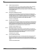
Appendix C RAID Controller Considerations Embedded MegaRAID Controller Installing a SCU Upgrade ROM Module For Embedded RAID SAS Support The SCU Upgrade ROM module contains a chip on a small circuit board. This module attaches to a motherboard header (see Figure C-1). This chip adds SAS support for up to eight drives. To install a SCU upgrade ROM jumper, follow these steps: Step 1 Locate the SCU_ROM header (see Figure C-1).
Appendix C RAID Controller Considerations Embedded MegaRAID Controller Installing a Software RAID Key Module for Embedded RAID 5 Support The software RAID key module contains a chip on a small circuit board. This module attaches to a motherboard header. This chip upgrades SAS support to add RAID 5 support (RAID 0, 1, 5, and 10 for up to eight drives). See Figure C-1. Note You must have the RAID SCU upgrade ROM installed and before you can use the RAID 5 key.
Appendix C RAID Controller Considerations Embedded MegaRAID Controller Launching the LSI Embedded RAID Configuration Utility Launch the utility by pressing Ctrl+M when you see the prompt during system boot. For more information about using the Embedded MegaRAID software to configure your disk arrays, see the LSI Embedded MegaRAID Software User Guide.
Appendix C RAID Controller Considerations Embedded MegaRAID Controller Downloading the LSI MegaSR Drivers The MegaSR drivers are included in the C-series driver ISO for your server and OS. Download the drivers from Cisco.com: Step 1 Find the drivers ISO file download for your server online and download it to a temporary location on your workstation: a. See the following URL: http://www.cisco.com/cisco/software/navigator.html b. Click Unified Computing and Servers in the middle column. c.
Appendix C RAID Controller Considerations Embedded MegaRAID Controller Step 4 Step 5 Start the Windows driver installation using one of the following methods: • To install from local media: Connect an external USB DVD drive to the server and then insert the first Windows install disc into the drive. Skip to Step 6. • To install from remote ISO: Log in to the server’s CIMC interface and continue with the next step. Launch a Virtual KVM console window and select the Virtual Media tab. a.
Appendix C RAID Controller Considerations Embedded MegaRAID Controller Linux Driver Installation This section explains the steps to install the embedded MegaRAID device driver in a Red Hat Enterprise Linux installation or a SuSE Linux Enterprise Server installation.
Appendix C RAID Controller Considerations Embedded MegaRAID Controller Step 4 If necessary, use this command to change the file name of the driver update disk to a name with fewer than eight characters: copy dud-[driver version].img dud.img Step 5 Open the DOS Command Prompt and navigate to the directory where raw write.exe is located. Step 6 Type the following command to create the installation diskette: raw write Step 7 Press Enter. You are prompted to enter the name of the boot image file.
Appendix C RAID Controller Considerations Embedded MegaRAID Controller Installing the Red Hat Linux Driver This section describes the fresh installation of the Red Hat Enterprise Linux 5.7, 6.1, or 6.2 device driver on systems with the embedded MegaRAID stack. Step 1 Create a RAID drive group using the LSI SWRAID Configuration utility before you install this driver for the OS. Launch this utility by pressing Ctrl+M when LSI SWRAID is shown during BIOS post. Step 2 Prepare the dud.
Appendix C RAID Controller Considerations Embedded MegaRAID Controller Step 10 Press Enter. The prompt asks whether you have a driver disk. Step 11 Use the arrow key to select Yes, and then press Enter. Step 12 Select fd0 to indicate that you have a floppy diskette with the driver on it.
Appendix C RAID Controller Considerations Embedded MegaRAID Controller c. Select the check box in the Mapped column for the media that you just added, then wait for mapping to complete. Step 6 Power cycle the server. Step 7 Press F6 when you see the F6 prompt during bootup. The Boot Menu window opens. Step 8 On the Boot Manager window, select the physical disc or virtual DVD and press Enter. The SLES installation begins when the image is booted.
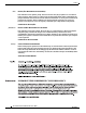
Appendix C RAID Controller Considerations RAID Controller Cabling RAID Controller Cabling This section includes the following topics: • Cable Routing, page C-17 • Cisco UCS C24 Server RAID Cabling Instructions, page C-18 Cable Routing The RAID controller connectors in this server are shown in Figure C-2.
Appendix C RAID Controller Considerations RAID Controller Cabling Cisco UCS C24 Server RAID Cabling Instructions This section contains the following topics: • Backplane and Expander Options, page C-18 • Small Form Factor 24-Drive Backplane With Expander Cabling, page C-18 • Small Form Factor 16-Drive Backplane (No Expander) Cabling, page C-19 • Large Form Factor 12-Drive Backplane With Expander Cabling, page C-20 Backplane and Expander Options The server is orderable in three different versions,
Appendix C RAID Controller Considerations RAID Controller Cabling Step 1 Connect SAS cable 1 from card connector SAS 0 to the Port0 connector on the expander. Step 2 Connect SAS cable 2 from card connector SAS 1 on the card to the Port1 connector on the expander. Step 3 If you are using the 9265CV-8i card, you can also install an SCPM for RAID backup. Install the SCPM (see Replacing a SuperCap Power Module (RAID Backup Unit), page 3-39), then attach the cable from the card to the SCPM.
Appendix C RAID Controller Considerations RAID Controller Cabling Second Controller (Drives 9 through 16, Cable UCSC-CABLE-A8): The required UCSC-CABLE-A8 cable kit has two mini-SAS cables. To control 16 drives in this configuration, you must add a second controller card to control drives 9–16. Cable 3 controls drives 9–12 and cable 4 controls drives 13–16.
Appendix C RAID Controller Considerations Restoring RAID Configuration After Replacing a RAID Controller Restoring RAID Configuration After Replacing a RAID Controller When you replace a RAID controller, the RAID configuration that is stored in the controller is lost. Use the following procedure to restore your RAID configuration to your new RAID controller. Step 1 Replace your RAID controller. See Replacing a PCIe Card, page 3-34.
Appendix C RAID Controller Considerations For More Information Cisco UCS C24 Server Installation and Service Guide C-22 OL-26647-01
A P P E N D I X D Installation for Cisco UCS Integration The Cisco UCS integration instructions have been moved to the integration guides found here: Cisco UCS C-Series Server Integration with UCS Manager Guides Refer to the guide that is for the version of Cisco UCS Manager that you are using.
Appendix D Installation for Cisco UCS Integration Cisco UCS C24 Server Installation and Service Guide D-2 OL-26647-01