
Network Router User Manual


3-8
ATM Switch Router Software Configuration Guide
OL-7396-01
Chapter 3 Initially Configuring the ATM Switch Router
Configuring the IP Interface
Note These IP connections are used only for network management.
To configure the switch to communicate via the Ethernet interface, provide the IP address and subnet
mask bits for the interface.
This section includes the following:
• Configuring IP Address and Subnet Mask Bits, page 3-8
• Testing the Ethernet Connection, page 3-9
Configuring IP Address and Subnet Mask Bits
Define subnet mask bits as a decimal number between 0 and 22 for Class A addresses, between 0 and 14
for Class B addresses, or between 0 and 6 for Class C addresses. Do not specify 1 as the number of bits
for the subnet field. That specification is reserved by Internet conventions.
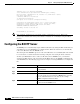
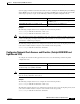
To configure the IP address, perform the following steps, beginning in global configuration mode:
Note Since release 12.0(1a)W5(5b) of the ATM switch software, addressing the interface on the processor
(CPU) has changed. The ATM interface is now called atm 0, and the Ethernet interface is now called
ethernet 0. The old formats (atm 2/0/0 and ethernet 2/0/0) are still supported.
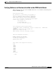
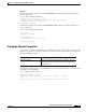
Example
The following example shows how to configure interface ethernet 0 with IP address 172.20.40.93 and
subnetwork mask 255.255.255.0:
Switch(config)# interface ethernet 0
Switch(config-if)# ip address 172.20.40.93 255.255.255.0
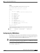
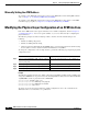
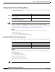
Displaying the IP Address
To display the IP address configuration, use the following privileged EXEC commands:
Command Purpose
Step 1
Switch(config)# interface ethernet 0
Switch(config-if)#
Selects the interface to be configured.
Step 2
Switch(config-if)# ip address ip-address mask Configures the IP and subnetwork address.
Command Purpose
show interfaces ethernet 0 Displays the Ethernet interface IP address.
more system:running-config Shows the physical layer scrambling
configuration.