QUICK START GUIDE Cisco ASR 1002 Router 1 Documentation and Resources 2 Prepare for Installation 3 Rack-Mount the Router 4 Connect the Router to the Network 5 Start the System 6 Configuring the Router 7 After Installation
1 Documentation and Resources Documentation for the Cisco 1000 Series Aggregation Services Routers documentation is online with the exception of the regulatory compliance and safety documentation and the Cisco 1000 Series Aggregation Services Routers documentation flyer. For detailed hardware installation instructions, refer to the online Cisco Series 1000 Aggregation Services Routers Hardware Installation and Initial Configuration Guide.
2 Prepare for Installation This section contains information about tools and parts, warnings, site preparation information, and information for rack-mount and equipment shelf or tabletop installation. Warning Only trained and qualified personnel should install, replace, or service this equipment. Statement 1030 Caution The eUSB panel door on the side of the Cisco ASR 1002 Router must not be opened. If there is a problem with eUSB flash card, the chassis should be returned.
Prepare for Rack-Mount Installation Before you begin the rack-mounting tasks: • Decide whether or not you want to front-mount or rear-mount the chassis. • Decide whether or not you want to attach cable-management brackets to your chassis. Note If you install cable-management brackets, make certain that you use the specified rack-mount ear holes as stated in the procedure and install the brackets after the cassia is mounted in the equipment rack.
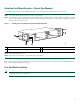
Attach the Rack-Mount Brackets—Chassis Rear-Mounted To install the rack-mount on a Cisco ASR 1002 Router for a rear rack-mount configuration, follow these steps: Step 1 Locate the threaded ear holes in the rear sides of the chassis. Step 2 Position the rear rack-mount bracket top hole with the chassis from the back (See Figure 2).Make certain that you hold the rear rack-mount bracket with the ear holes facing outward and towards the rear of the chassis.
Figure 3 shows the Cisco ASR 1002 Router in a four-post rack.
Tip To allow space to attach the cable-management brackets to the chassis in the rack easily, make certain that you use the rack-mount bracket ear holes specified in Step 9. Step 8 Hold the chassis in position against the mounting rails and follow these steps: a. Insert the bottom screw into the second ear hole from the bottom of the rack-mount ear and use a hand-held screwdriver to tighten the screw to the rack rail. b.
If you are using a two-post rack, secure the rack to the floor surface to prevent tipping and avoid bodily injury and component damage. Caution Step 1 Position the chassis so the front is closest to you and lift it carefully into the rack. To prevent injury, avoid any sudden twists or moves. Step 2 Slide the chassis into the rack, pushing it back until the rack-mount brackets meet the mounting strips or posts on both sides of the rack.
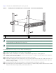
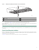
Figure 5 Attaching the Cable-Management Bracket to the Cisco ASR 1002 Router SPA-4XOC3-PO AT ST C/ A/L A C/ A US 2 1 A/L A C/ SPA-4XOC3-PO S 1 2 3 A/L A C/ S 3 C/ PWR STAT 0 A C/ C/ A/L A min 3 S SPA-4XOC3-PO 2 A/L crit A/L C/ A C/ A/L A maj 280280 0 pwr CON MGMT 0 LINK A/L QE1 MTS ASR 1002 stat 2 QE0 CARRIER ST AT US STAT BOOT 1 3 QE3 A/L AUX QE2 A/L A C/ A/L A C/ A/L A C/ A ST AT US 1 1 1 Secure the cable-management bottom screw an
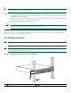
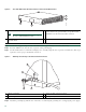
Figure 6 Cisco ASR 1002 Router Ground Connector Location and eUSB Panel Door STA A/L A/L 3-POS SPA-4XOC 2 C/A A/L A/L C/A 1 C/A STA TUS 3 A/L PWR STAT 2 CON MGMT 0 LINK CARRIER 3-POS SPA-4XOC 2 3 BOOT A/L QE3 C/A QE2 A/L QE1 1 QE0 A/L AUX MTS STAT C/A C/A C/A C/A TUS 1 TUS STA C/A A/L SPA-4XOC 3-POS 280283 0 1 2 3 crit A/L C/A C/A maj 4 A/L C/A min A/L pwr 0 ASR 1002 stat 3 1 F0 with Cisco ASR1000-ESP5 or Cisco ASR1000-ESP10 Note 2 3 The
Step 5 Locate the chassis ground connector on the side of your chassis. Step 6 Insert the two screws through the holes in the grounding lug. Step 7 Use the Number 2 Phillips screwdriver to carefully tighten the screws until the grounding lug is held firmly to the chassis. Do not overtighten the screws. Step 8 Connect the opposite end of the grounding wire to the appropriate grounding point at your site to ensure an adequate chassis ground.
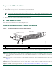
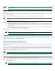
Cisco ASR 1002 Integrated Route Processor Console and Auxiliary Port Connectors 1 2 C/A QE1 QE3 BOOT C/A ST AT US 0 ASR 1002 A/L A/L 3-POS SPA-4XOC 0 1 2 3 crit A/L C/A C/A C/A min maj A/L stat pwr 1 0 C/A QE2 CON MGMT A/L QE0 LINK 1 STAT MTS A/L PWR STAT AUX CARRIER 280285 Figure 8 1 CON—console port AUX—auxiliary port 2 Step 3 After you establish normal router operation, you can disconnect the terminal.
Step 3 Configure to a fixed speed through the command-line interface (CLI) commands. Connect the Shared Port Adapter Cables The instructions for connecting the cables for the shared port adapters installed in the Cisco ASR 1002 Router are contained in the Cisco ASR 1000 Series Aggregation Services Routers SPA and SIP Hardware Installation Guide.
Proceed to the “Start the System” section on page 14 to complete the installation. 5 Start the System Before you start the system, you must connect power to it. Connect AC Power to the Cisco ASR 1002 Router This section provides instructions for installing the AC power supply into the Cisco ASR 1002 Router. Read the safety warnings before you begin. Warning Never install an AC power module and a DC power module in the same chassis.
AC Power Supply for the Cisco ASR 1002 Router 1 2 3 4 OUTPUT INPUT FAIL 0 OK 5 6 FAN OUTPUT INPUT OK FAIL This unit might have more than one power supply connection. All connections must be removed to de-energize the unit. OK FAN OK This unit might have more than one power supply connection. All connections must be removed to de-energize the unit.
Figure 12 shows the DC power supply for the Cisco ASR 1002 Router. DC Power Supply for the Cisco ASR 1002 Router 1 2 3 4 OUTPUT INPUT FAIL 0 OK 5 6 FAN OUTPUT INPUT OK FAIL This unit might have more than one power supply connection. All connections must be removed to de-energize the unit. OK FAN OK This unit might have more than one power supply connection. All connections must be removed to de-energize the unit.
The color coding of the DC-input power supply leads depends on the color coding of the DC power source at your site. Typically, green or green/yellow is used for ground. Make certain the lead color coding you choose for the DC-input power supply matches lead color coding used at the DC power source. Note Warning When you install the unit, the ground connection must always be made first and disconnected last.
Step 9 Connect the ground, positive, and negative leads to the power source. Step 10 Turn the branch source breaker on. Step 11 Turn the power supply switch to the On (I) position. Step 12 Verify that the LEDs illuminate. This completes the procedure for connecting DC-input power. Verifying Power Supply operation Follow this procedure to verify power supply is operating correctly.
Step 1 Turn on power. The green OK LED on the power supply turns on. (Both power supplies are required in the Cisco ASR 1002 Router.) Step 2 Listen for the fans; you should immediately hear them operating. Step 3 During the boot process, observe the system LEDs. The power LED should be green. The STATUS LED lights yellow to indicate booting and then green when Cisco IOS is running. Table 3 provides information about the LEDs as the system starts.
Table 4 provides information about the Cisco ASR1000-ESP5 LEDs in the Cisco ASR 1002 Router as the system starts. Table 4 Cisco ASR1000-ESP5 and ASR1000-ESP10 LED Activity LED Label LED Color Behavior Description PWR Power Solid green All power supplies are within operational limits. Off The router is in standby mode. Green Code has successfully downloaded and is operational. Yellow BOOT ROM has successfully loaded. Red Not booted.
%IOSXEBOOT-4-DEBUG_CONF: (rp/0): Using DEBUG_CONF file /misc/scratch/debug.conf Feb 13 13:00:38.546 R0/0: %PMAN-3-PROCFAIL_IGNORE: All process failures are being ignored due to debug settings. FRU may not reset automatically Restricted Rights Legend Use, duplication, or disclosure by the Government is subject to restrictions as set forth in subparagraph (c) of the Commercial Computer Software - Restricted Rights clause at FAR sec. 52.
*Feb 13 13:01:28.701: %LINK-5-CHANGED: Interface GigabitEthernet0, changed state to administratively down *Feb 13 13:01:29.728: %LINEPROTO-5-UPDOWN: Line protocol on Interface GigabitEthernet0, changed state to down *Feb 13 13:01:14.738: %CPPHA-7-SYSREADY: F0: cpp_ha: CPP client process FMAN-FP (5 of 5) ready. *Feb 13 13:01:14.895: %IOSXE-6-PLATFORM: F0: cpp_cp: cpp_mlp_svr_client_bind: cpp_mlp_svr_ifm_init() successful *Feb 13 13:01:15.
Router> enable Step 3 At the password prompt, enter your system password. If an enable password has not been set on your system, this step may be skipped. The following example shows entry of the password called enablepass: Password: enablepass Step 4 When your enable password is accepted, the privileged EXEC configuration mode prompt appears: Router# Step 5 Step 6 You now have access to the CLI in privileged EXEC mode and you can enter the necessary commands to complete your desired tasks.
for management of the system, extended setup will ask you to configure each interface on the system Would you like to enter basic management setup? [yes/no]: n First, would you like to see the current interface summary? [yes]: y Any interface listed with OK? value "NO" does not have a valid configuration Interface GigabitEthernet0/0/0 GigabitEthernet0/0/1 GigabitEthernet0/0/2 GigabitEthernet0/0/3 GigabitEthernet0 IP-Address unassigned unassigned unassigned unassigned unassigned OK? NO NO NO NO YES Method
no ip address ! interface GigabitEthernet0/0/1 shutdown no ip address ! interface GigabitEthernet0/0/2 shutdown no ip address ! interface GigabitEthernet0/0/3 shutdown no ip address ! interface GigabitEthernet0/1/0 shutdown no ip address ! interface GigabitEthernet0/1/1 shutdown no ip address ! interface FastEthernet0/3/0 shutdown no ip address ! interface FastEthernet0/3/1 shutdown no ip address ! interface FastEthernet0/3/2 shutdown no ip address ! interface FastEthernet0/3/3 shutdown no ip address ! inte
Enter your selection [2]: Router#reload Proceed with reload? [confirm] *Jan 11 06:59:29.476: %SYS-5-RELOAD: Reload requested by console. Reload Reason: Reload command. System Bootstrap, Version 12.2(20071105:235056) [gschnorr-mcp_rommon_rel_1_25 101], DEVELOPMENT SOFTWARE Copyright (c) 1994-2007 by cisco Systems, Inc.
Use, duplication, or disclosure by the Government is subject to restrictions as set forth in subparagraph (c) of the Commercial Computer Software - Restricted Rights clause at FAR sec. 52.227-19 and subparagraph (c) (1) (ii) of the Rights in Technical Data and Computer Software clause at DFARS sec. 252.227-7013. cisco Systems, Inc. 170 West Tasman Drive San Jose, California 95134-1706 Cisco IOS Software, IOS-XE Software (PPC_LINUX_IOSD-ADVIPSERVICESK9-M), Experimental Version 12.
Save the Running Configuration to NVRAM To store the configuration or changes to your startup configuration in NVRAM, use the copy running-config startup-config command to save your configuration changes to the startup configuration so that the changes will not be lost if the software reloads or a power outage occurs. For example: Router# copy running-config startup-config Building configuration... It might take a minute or two to save the configuration.
Power Off the Cisco ASR 1002 Router This section explains how to shut down the Cisco ASR 1002 Router. It is recommended that before turning off all power to the chassis, you issue the reload command. This insures that the operating system cleans up all the file systems. Once the reload operation is complete, then the Cisco ASR 1000 Series router can be powered off safely.
Step 2 Using the handles on both sides of the module, with two hands, gently insert the Cisco ESP5 or -ESP10 into the top chassis slot. Note Handle the Cisco ESP5 and ESP10 by the carrier edges only; never touch the printed circuit board components or connector pins. Step 3 Once the board is seated, tighten the captive screws. Step 4 Place the Cisco ESP5 or Cisco ESP10 on an antistatic surface with its printed circuit board components facing upward or in a static shielding bag.
Step 9 Power on the router by turning the power switch to the on (I) position. Replace a Power Supply in the Cisco ASR 1002 Router This section provides instructions for removing and replacing the AC power supply and the DC power supply in a Cisco ASR 1002 Router. Before you begin, make certain the chassis is grounded. Two power supplies must be installed in the chassis at all times to ensure sufficient cooling. The system fans are inside the power supply units and must spin for cooling.
Figure 14 Cisco ASR 1002 Router AC Power Cord OUTPUT INPUT FAIL FAN OK OK 280383 This unit might one power have more than sup All connec ply connection. tion to de-ene s must be remove rgize the d unit. 1 1 AC power cord and service loop b. Take the power cord and run it below the handles of the power supply in slot 1 (the power supply you are connecting) and the power supply in slot 0 (left) as shown in Figure 15.
Note Using a tie wrap for the AC power cable is optional and not necessary. However, if you do attach the AC power cable to a power supply tab and then you remove the AC power cable for some reason, check for any damage to the cable after you cut the tie wrap off. If the power cord is damaged, replace it immediately. Note Turn the power supply switch to On (I) after both sides of the power cord are connected. Step 6 Plug the AC power supply cable into the AC power source.
Step 7 Replace the DC power supply within five minutes or the system will shutdown. You have completed the procedure for removing a DC power supply from the Cisco ASR 1002 Router. Installing the DC Power Supply This section provides information about replacing a DC power supply in the Cisco ASR 1002 Router. The color coding of the DC-input power supply leads depends on the color coding of the DC power source at your site. Typically, green or green/yellow is used for ground.
Figure 18 Cisco ASR 1002 Router DC Power Supply 4 OUTPUT INPUT FAIL OK FAN OK This unit might one power have more than sup All connec ply connection. tion to de-ene s must be remove rgize the d unit. 3 2 16A 280290 -48V/-60V 1 1 Ground lead wire 3 Positive lead wire 2 Negative lead wire 4 DC power supply Standby switch Step 5 Insert the stripped end of the ground lead all the way into the ground lead receptacle on the DC-input power supply, and tighten the receptacle screw using a 3.
Americas Headquarters Cisco Systems, Inc. 170 West Tasman Drive San Jose, CA 95134-1706 USA www.cisco.com Tel: 408 526-4000 800 553-NETS (6387) Fax: 408 527-0883 Asia Pacific Headquarters Cisco Systems, Inc. 168 Robinson Road #28-01 Capital Tower Singapore 068912 www.cisco.com Tel: +65 6317 7777 Fax: +65 6317 7799 Europe Headquarters Cisco Systems International BV Haarlerbergpark Haarlerbergweg 13-19 1101 CH Amsterdam The Netherlands www-europe.cisco.