QUICK START GUIDE Cisco ASR 1004 Router 1 Documentation and Resources 2 Prepare for Installation 3 Rack-Mount the Router 4 Connect the Router to the Network 5 Start the System 6 Configure the Router 7 After Installation
1 Documentation and Resources Documentation for the Cisco 1000 Series Aggregation Services Routers documentation is online with the exception of the regulatory compliance and safety documentation and the Cisco 1000 Series Aggregation Services Routers documentation flyer. For detailed hardware installation instructions, refer to the online Cisco Series 1000 Aggregation Services Routers Hardware Installation and Initial Configuration Guide.
2 Prepare for Installation This section contains information about tools and parts, warnings, site preparation information, and information for rack-mount and equipment shelf or tabletop installation. Warning Only trained and qualified personnel should install, replace, or service this equipment. Statement 1030 Before beginning this router installation, read the Regulatory Compliance and Safety Information for the Cisco 1000 Series Aggregation Services Routers document.
Prepare for Rack-Mount Installation Before you begin the rack-mounting tasks: • Decide whether or not you want to front- mount or rear-mount the chassis • Decide whether or not you want to attach cable-management brackets to your chassis. Note If you install cable management brackets, make certain that you use the specified rack-mount ear holes as stated in the procedure.
Step 6 To install the Cisco ASR 1004 Router in an equipment rack, see “Four-Post Rack Installation” section on page 6 or “Two-Post Rack Installation” section on page 8. Note If you install cable management brackets, make certain that the chassis is mounted in the equipment rack first.
Four-Post Rack Installation This section describes the types of racks used for rack-mounting the chassis.
Step 5 Lift the chassis into position between the rack posts (requires two people). Step 6 Align the mounting bracket holes with the rack post holes and attach the chassis to the rack. At this point, if there is a third person, then that person can insert the screws while the other two people hold that chassis in place, unless the chassis is resting on a shelf. Step 7 Position the chassis until the rack-mounting flanges are flush against the mounting rails on the rack.
Two-Post Rack Installation The Cisco ASR 1004 Router can be installed in a two-post rack, either 19 inch or 23 inch. Inner clearance (the width between the inner sides of the two posts or rails) must be at least 19 inches (48.26 cm). The height of the chassis is 1.73 inches (4.39 cm). Airflow through the chassis is from front to back.
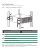
Step 4 Hold the chassis in position against the mounting rails and follow these steps: a. Insert the bottom screw into the third hole up from the bottom of the rack mount ear and use a hand-held screwdriver to tighten the screw to the rack rail (see Figure 4). Insert the bottom screw first and then the second screw at the top of the chassis diagonally from the bottom screw. This helps secure the chassis in place while you insert the other screws. Tip b.
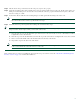
Figure 5 Attaching the Cable-Management Bracket to the Cisco ASR 1004 Router A C/ A/L C/ A A/L A C/ C/ C/ A/L A C/ 3 A/L 2 C/ A 3 A US C/ ST AT A/L A C/ A/L A C/ 1 2 3 A/L A C/ A/L -POS SPA-4XOC3 A C/ ST AT US 0 3 A/L A C/ A/L ST AT US A/L A C/ A/L A C/ A/L -POS SPA-4XOC3 2 1 0 A C/ ST AT US A/L C/ A A/L A C/ A/L -POS SPA-4XOC3 2 A C/ -POS SPA-4XOC3 0 1 280176 2 A/L 3 A/L A/L A 1 A C/ A/L A C/ A/L 3 2 1 1 -POS SPA-4XOC3 1 A C/ ST AT US A/L A C/ A
C/A C/A A/L A/L C/A 3 C/A 2 A/L C/A A/L ST AT US C/A A/L A/L 1 0 C/A C/A 3 2 C/A A/L C/A A/L 3 C/A 2 A/L A/L C/A 1 0 3 SPA-4XOC3-POS 2 A/L ST AT US 1 C/A C/A A/L A/L SPA-4XOC3-POS ST AT US A/L 0 3 C/A 2 C/A SPA-4XOC3-POS 1 SPA-4XOC3-POS A/L A/L C/A C/A US ST AT C/A A/L C/A A/L C/A A/L SPA-4XOC3-POS 0 1 2 A/L 3 280179 C/A A/L SPA-4XOC3-POS 0 ST AT US 2 A/L 1 0 C/A A/L 1 0 C/A A/L A/L C/A 3 SPA-4XOC3-POS 3 A/L A/L A/L C/A C/A 2 A
Step 5 Locate the chassis ground connector on the side of your chassis. Step 6 Insert the two screws through the holes in the grounding lug. Step 7 Use the Number 2 Phillips screwdriver to carefully tighten the screws until the grounding lug is held firmly to the chassis. Do not overtighten the screws. Step 8 Connect the opposite end of the grounding wire to the appropriate grounding point at your site to ensure an adequate chassis ground.
Step 2 After you establish normal router operation, you can disconnect the terminal. Note For console and auxiliary port pinouts, see Appendix A in the Cisco ASR 1000 Series Aggregation Services Routers Hardware Installation and Initial Configuration Guide.
Step 3 Insert an Ethernet RJ-45 cable into the MGMT ETHERNET port. Step 4 Insert the other end of the RJ-45 cable to your management device or network. Step 5 Configure to a fixed speed through the command line interface (CLI) commands. Connect the Shared Port Adapter Cables The instructions for connecting the cables for the shared port adapter installed in the Cisco ASR 1004 Router are contained in the Cisco ASR 1000 Series Aggregation Services Routers SPA and SIP Hardware Installation Guide.
Step 3 Insert the AC power cable into the power supply inlet. Step 4 Plug the power supply cable into the power source. Step 5 The power supply LEDs light when power is supplied to the router.
Warning This equipment must be grounded. Never defeat the ground conductor or operate the equipment in the absence of a suitably installed ground conductor. Contact the appropriate electrical inspection authority or an electrician if you are uncertain that suitable grounding is available. Statement 1024 Warning This unit might have more than one power supply connection. All connections must be removed to de-energize the unit.
Figure 10 shows the DC power supply for the Cisco ASR 1004 Router.
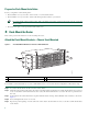
Figure 11 DC Power Supply Grounding Stud Location and Connection on the Cisco ASR 1004 Router 4 2 280034 3 1 1 DC power supply grounding stud 3 DC power supply chassis grounding stud location 2 Grounding stud screws 4 Earth ground symbol Step 1 Make certain that the chassis ground is connected before you begin installing the DC power supply.
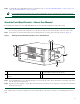
Figure 12 Cisco ASR 1004 Router DC Power Supply Terminal Block 2 280187 1 5 4 3 1 Ground lug and positive lead wire 4 Washer 2 Terminal block and positive stud 5 Kepnut screw 3 Earth grounding symbol Caution Before you continue to install the terminal block wires, stop and perform Step 3 to prevent any contact with metal lead on the ground wire. Step 3 You must wrap the positive and negative cables with sleeving.
Step 8 Connect the other ends of the terminal block cables to the site ground connection. Move the circuit-breaker switch to the On position (|). This completes the procedure for connecting DC-input power. Your installation is complete. Proceed to the “Start the System” section on page 14 to start the router. Note After powering off the router, wait a minimum of 30 seconds before powering it on again. Verifying Power Supply Operation Follow this procedure to verify power supply is operating correctly.
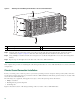
– Make certain that each shared port adapter is firmly seated in its subslot and its captive screws are securely tightened. – The Cisco ASR1000-ESP10 forwarding processor in the Cisco ASR 1004 router is inserted in slot F0, is firmly seated in its slot, and its captive screws are securely tightened. – All network interface cables are connected. – The console terminal is turned on. Step 2 Turn on power. The green OK LED on the power supply turns on.
Located rp_super.ppc.nader.5g.evfc.bin Image size 211681484 inode num 12, bks cnt 51681 blk size 8*512 ######################################################################################################### ############## ############## ############################################# Boot image size = 211681484 (0xc9e00cc) bytes Using midplane macaddr Package header rev 0 structure detected Calculating SHA-1 hash...
32768K bytes of non-volatile configuration memory. 1869396K bytes of physical memory. 7798783K bytes of eUSB flash at bootflash:. --- System Configuration Dialog --Would you like to enter the initial configuration dialog? [yes/no]: no Press RETURN to get started! *Feb 19 17:34:27.361: % Error opening nvram:/ifIndex-table No such file or directory *Feb 19 17:34:28.
Step 6 *Feb 19 17:35:22.221: %CRYPTO-6-ISAKMP_ON_OFF: ISAKMP is OFF Router> 6 Configure the Router Use this section for information on configuring the Cisco ASR 1004 Router. Using the Console Interface To access the command line interface using the console, follow these steps: Step 1 Once the terminal console port is connected, configure your terminal emulation software with valid settings.
Basic management setup configures only enough connectivity for management of the system, extended setup will ask you to configure each interface on the system. --- System Configuration Dialog --Would you like to enter the initial configuration dialog? [yes/no]: y At any point you may enter a question mark '?' for help. Use ctrl-c to abort configuration dialog at any prompt. Default settings are in square brackets '[]'.
enable password tests line vty 0 4 password test no snmp-server ! ip routing no bridge 1 no clns routing ! interface GigabitEthernet0/0/0 shutdown no ip address ! interface GigabitEthernet0/0/1 shutdown no ip address ! interface GigabitEthernet0/0/2 shutdown no ip address ! interface GigabitEthernet0/0/3 shutdown no ip address ! interface GigabitEthernet0/1/0 shutdown no ip address ! interface GigabitEthernet0/1/1 shutdown no ip address ! interface FastEthernet0/3/0 shutdown no ip address ! interface FastEt
shutdown no ip address dialer-list 1 protocol ip permit dialer-list 1 protocol ipx permit ! end [0] Go to the IOS command prompt without saving this config. [1] Return back to the setup without saving this config. [2] Save this configuration to nvram and exit. Enter your selection [2]: Router#reload Proceed with reload? [confirm] *Jan 11 06:59:29.476: %SYS-5-RELOAD: Reload requested by console. Reload Reason: Reload command. System Bootstrap, Version 12.
zimage at: initrd at: isord at: avail ram: 00807673 009B9000 01007000 00400000 009B8E53 01006E53 0CD2A000 00800000 Kernel load: Uncompressing image... dst: 00000000 lim: 00400000 start: 00807673 size: 001B17E0...done. Now booting the IOS XE kernel %IOSXEBOOT-4-BOOT_PARAMETER: (rp/0): Booting with custom BOOT_PARAM setting %IOSXEBOOT-4-DEBUG_CONF: (rp/0): File /misc/scratch/debug.
Note Basic management setup configures enough connectivity for managing the system; extended setup will ask you to configure each interface on the system. For detailed information about setting global parameters, refer to the Cisco ASR 1000_Series Aggregation Services Routers Software Configuration Guide.
7 After Installation Follow the instructions in this section to replace components after installation. The following topics are covered in this section: • Power Off the Cisco ASR 1004 Router, page 30 • Remove and Replace a Power Supply, page 30 • Remove the Shared Port Adapter, page 35 Warning Only trained and qualified personnel should be allowed to install, replace, or service this equipment.
Note Caution Two power supplies must be installed in the chassis at all times to ensure sufficient cooling. The system fans are inside the power supply units and must spin for cooling. Because all the system fans can be powered by one power supply, the second power supply unit does not have to be powered on, but it must be installed. If you remove a power supply, the system can run for a maximum of five minutes before the system shuts down.
b. Unscrew the positive cable Kepnut screw, washer, and ground lug, and remove the stud and lead wire. c. Unscrew the earth ground Kepnut screw, washer, and ground lug and remove the stud and lead ground wire. Step 6 Loosen the captive screws on the DC power supply. Note Caution Two power supplies must be installed in the chassis at all times to ensure sufficient cooling. The system fans are inside the power supply units and must spin for cooling.
Figure 13 Cisco ASR 1004 Router DC Power Supply Grounding Wire and Stud All measurements in inches 2.24 End View Ø 0.267 2 holes 0.48 0.25 0.63 25527 Crimp area 0.37 0.08 Step 5 Attach the other end of the ground cable to the site ground connection. Before you continue to install the terminal block ground wires, stop and perform Step 6. To prevent any contact with metal lead on the ground wire and the plastic cover. Caution Step 6 You must wrap the positive and negative cables with sleeving.
Step 8 Tighten the Kepnut screw (use the screwdriver to tighten the ground screw in the terminal block to a torque of 8 in-lbs / 4 per.) and repeat the same steps for the positive ground stud and wire. Note Step 9 Secure the wires coming in from the terminal block so that they cannot be disturbed by casual contact. Use tie wraps to secure the wires, so that the wires are not pulled from the terminal block by casual contact. Ti-wrap studs are located below the power supply terminal block.
Step 6 To remove the SIP, first disconnect all cables from each SPA. Step 7 Loosen the locking thumbscrews on both sides of the SIP. Step 8 Slide the SIP out of the module slot. If you are removing a blank filler plate, pull the blank filler plate completely out of the module slot. Remove the Shared Port Adapter The shared port adapter ships installed. These instructions are provided for future use. Cabling information is included with the specific shared port adapter documentation.
Caution The shared port adapter must slide into the slot guides under the chassis lid. Do not allow the shared port adapter components to come in contact with the system board or the shared port adapter could be damaged. Step 6 Carefully slide the shared port adapter into the shared port adapter slot and seat it. When installed, the shared port adapter input/output panel should be flush with the face of the router.
Americas Headquarters Cisco Systems, Inc. 170 West Tasman Drive San Jose, CA 95134-1706 USA www.cisco.com Tel: 408 526-4000 800 553-NETS (6387) Fax: 408 527-0883 Asia Pacific Headquarters Cisco Systems, Inc. 168 Robinson Road #28-01 Capital Tower Singapore 068912 www.cisco.com Tel: +65 6317 7777 Fax: +65 6317 7799 Europe Headquarters Cisco Systems International BV Haarlerbergpark Haarlerbergweg 13-19 1101 CH Amsterdam The Netherlands www-europe.cisco.