Cisco IOS XE Integrated Session Border Controller Configuration Guide for the Cisco ASR 1000 Series Aggregation Services Routers Cisco IOS XE Release 2.1 May 5, 2008 Americas Headquarters Cisco Systems, Inc. 170 West Tasman Drive San Jose, CA 95134-1706 USA http://www.cisco.
THE SPECIFICATIONS AND INFORMATION REGARDING THE PRODUCTS IN THIS MANUAL ARE SUBJECT TO CHANGE WITHOUT NOTICE. ALL STATEMENTS, INFORMATION, AND RECOMMENDATIONS IN THIS MANUAL ARE BELIEVED TO BE ACCURATE BUT ARE PRESENTED WITHOUT WARRANTY OF ANY KIND, EXPRESS OR IMPLIED. USERS MUST TAKE FULL RESPONSIBILITY FOR THEIR APPLICATION OF ANY PRODUCTS.
CONTENTS Preface ix Document Revision History Objectives ix ix Intended Audience Organization x x Related Documentation xi Cisco ASR 1000 Series Router Documentation i-xi Cisco IOS Release 12.
Contents Configuring Primary IP and Primary Media IP Addresses: Example 2-10 Configuring Secondary IP and Secondary Media IP Addresses: Example 2-11 Making Global Changes to Controllers: Example 2-11 Making Changes to Individual Controller Settings: Example 2-13 Cisco H.
Contents Related Commands CHAPTER 6 5-7 H.248 Packages—Signaling and Control Contents 6-1 6-1 Enabling Optional H.248 Packages Related Commands 6-2 6-1 H.248 Address Reporting Package 6-2 H.248 Gate Information (Ginfo) Package Becomes Optional DBE Restrictions 6-2 H.248 Segmentation Package Support DBE Restrictions 6-3 Related Commands 6-3 6-2 6-2 H.248 Session Failure Reaction Package DBE Restrictions 6-4 6-3 H.
Contents DBE Restrictions 7-5 Local Source Properties (Address and Port) 7-5 Locally Hairpinned Sessions 7-5 Twice NAPT Pinhole Hairpinning 7-5 No NAPT Pinhole Hairpinning 7-5 DBE Restrictions 7-6 MGC-Specified Local Addresses or Ports DBE Restrictions 7-7 Multi-Stream Terminations DBE Restrictions 7-7 7-6 7-7 Nine-Tier Termination Name Hierarchy 7-7 Restrictions for Nine-Tier Termination Name Hierarchy 7-7 Information About Nine-Tier Termination Name Hierarchy 7-8 Displaying the Nine-Tier Terminati
Contents DBE Restrictions 8-3 Related Commands 8-3 IP NAPT Traversal Package and Latch and Relatch Support Latch and Relatch Support 8-3 DBE Restrictions 8-4 Related Commands 8-4 Local Source Properties (Address and Port) DBE Restrictions 8-5 NAPT and NAT Traversal 8-5 8-6 Traffic Management Policing 8-6 Two-Rate Three-Color Policing and Marking CHAPTER 9 Topology Hiding Contents 8-4 8-5 Remote Source Address Mask Filtering DBE Restrictions 8-6 Related Commands 8-6 Topology Hiding 8-3 8-6 9-1
Contents Hardware Redundancy 10-2 Software Redundancy 10-2 Route Processor Redundancy (RPR) CHAPTER 11 SSO Support 10-3 ISSU Support 10-3 10-2 Quality Monitoring and Statistics Gathering Contents 11-1 11-1 Billing and Call Detail Records 11-2 congestion-threshold Command DBE Status Notification 11-2 11-2 Enhanced Event Notification and Auditing 11-2 Retention and Returning of H.248 Event Information 11-3 Permanent H.248 Event Storage 11-3 H.
Preface This preface describes the objectives and organization of this document and explains how to find additional information on related products and services.
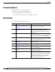
Preface Intended Audience This document is intended for the following people: • Experienced service provider administrators • Cisco telecommunications management engineers • Customers who use and manage Cisco ASR 1000 Series Routers Organization This document contains the following chapters: x Chapter Title Description 1 Integrated Session Border Controller Describes general architecture, list of supported for the Cisco ASR 1000 Series Routers features, and deployment scenario.
Preface Chapter Title Description 10 High Availability Support Describes hardware and software redundancy support for Integrated Session Border Controller on the Cisco ASR 1000 Series Routers. 11 Quality Monitoring and Statistics Gathering Describes DBE support for monitoring events, and generation of event notification, correct billing and call usage records.
Preface Command syntax descriptions use the following conventions: Convention Description bold Bold text indicates commands and keywords that you enter exactly as shown. italics Italic text indicates arguments for which you supply values. [x] Square brackets enclose an optional element (keyword or argument). | A vertical line indicates a choice within an optional or required set of keywords or arguments.
Preface Tip Means the following information will help you solve a problem. The tips information might not be troubleshooting or even an action, but could be useful information, similar to a Timesaver.
Preface xiv Cisco IOS XE Integrated Session Border Controller Configuration Guide for the Cisco ASR 1000 Series Aggregation Services Routers OL-15421-01
CH A P T E R 1 Integrated Session Border Controller for the Cisco ASR 1000 Series Routers Overview This chapter presents an overview of the Integrated Session Border Controller (SBC), supported features, and deployment of the Integrated Session Border Controller on the Cisco ASR 1000 Series Routers.
Chapter 1 Integrated Session Border Controller for the Cisco ASR 1000 Series Routers Overview General Overview The SBC functions break down into two logically distinct areas, as follows: • The signaling border element (SBE) function. SBEs may support functions that include interworking between various signaling protocols such as H.323 and Session Initiation Protocol (SIP), call admission control, advanced routing policy management, network attack detection, or call billing using RADIUS or DIAMETER.
Chapter 1 Integrated Session Border Controller for the Cisco ASR 1000 Series Routers Overview General Overview Figure 1-2 on page 1-3 illustrates the unified model. Figure 1-2 Unified SBC Model Domain A Domain B 271026 SBE+DBE The Integrated Session Border Controller runs under the distributed model and provides the DBE functionality. The distributed model offers advantages over the unified model, as follows: • Scalable to a larger number of sessions.
Chapter 1 Supported Integrated Session Border Controller Features Integrated Session Border Controller for the Cisco ASR 1000 Series Routers Overview Supported Integrated Session Border Controller Features The supported features roadmap lists the features documented in this guide, Cisco IOS XE Integrated Session Border Controller Configuration Guide for the Cisco ASR 1000 Series Aggregation Services Routers, and provides links to where they are documented.
Chapter 1 Integrated Session Border Controller for the Cisco ASR 1000 Series Routers Overview Supported Integrated Session Border Controller Features Related SBC Commands Chapter Where Documented Release Feature Name Cisco IOS XE Release 2.0 Extension to H.248 Audit Support None. Chapter 7, “H.248 Services—Signaling and Control” Cisco IOS XE Release 2.0 Extension to H.248 Termination Wildcarding Support None. Chapter 7, “H.248 Services—Signaling and Control” Cisco IOS XE Release 2.
Chapter 1 Supported Integrated Session Border Controller Features Integrated Session Border Controller for the Cisco ASR 1000 Series Routers Overview Chapter Where Documented Release Feature Name Related SBC Commands Cisco IOS XE Release 2.0 Integrated Session Border Controller High Availability None Chapter 10, “High Availability Support” Cisco IOS XE Release 2.
Chapter 1 Integrated Session Border Controller for the Cisco ASR 1000 Series Routers Overview Supported Integrated Session Border Controller Features Chapter Where Documented Release Feature Name Related SBC Commands Cisco IOS XE Release 2.0 MGC-Controlled Gateway-Wide Properties None. Chapter 6, “H.248 Packages—Signaling and Control” Cisco IOS XE Release 2.0 MGC-Specified Local Addresses or Ports None. Chapter 7, “H.248 Services—Signaling and Control” Cisco IOS XE Release 2.
Chapter 1 Deployment of the Integrated Session Border Controller Integrated Session Border Controller for the Cisco ASR 1000 Series Routers Overview Chapter Where Documented Release Feature Name Related SBC Commands Cisco IOS XE Release 2.0.1 transaction-pending command transaction-pending Cisco IOS Integrated Session Border Controller Command Reference Cisco IOS XE Release 2.
Chapter 1 Integrated Session Border Controller for the Cisco ASR 1000 Series Routers Overview Integrated Session Border Controller DBE Deployment Scenario This scenario requires the SP to provide capabilities such as opening pinholes for the duration of a conversation, and doing this without exposing the devices behind the firewall to malicious threats. In addition, given that voice is extremely sensitive to issues such as delay, latency, and packet loss, ensuring adequate performance is a challenge.
Chapter 1 Integrated Session Border Controller DBE Deployment Scenario 1-10 Integrated Session Border Controller for the Cisco ASR 1000 Series Routers Overview Cisco IOS XE Integrated Session Border Controller Configuration Guide for the Cisco ASR 1000 Series Aggregation Services Routers OL-15421-01
CH A P T E R 2 Configuring Integrated Session Border Controller This chapter describes fundamental configuration tasks required for typical data border element (DBE) deployment of the Integrated Session Border Controller (SBC). The Cisco ASR 1000 Series Aggregation Services Router serves as the DBE. The DBE operates with a Signaling Border Element (SBE), also called a media gateway controller (MGC).
Chapter 2 Configuring Integrated Session Border Controller Configuring Integrated Session Border Controller DBE Deployment • Transcoding • SBC virtual interface does not support any existing Cisco IOS features Configuring Integrated Session Border Controller DBE Deployment This section contains steps to configure a typical DBE on the Cisco ASR 1000 Series Routers.
Chapter 2 Configuring Integrated Session Border Controller Configuring Integrated Session Border Controller DBE Deployment DETAILED STEPS Step 1 Command or Action Purpose enable Enables privileged EXEC mode. • Enter your password if prompted. Example: Router> enable Step 2 configure terminal Enters global configuration mode.
Chapter 2 Configuring Integrated Session Border Controller Configuring Integrated Session Border Controller DBE Deployment Step 11 Command or Action Purpose control-address h248 ipv4 {A.B.C.D} Configures the DBE to use a specific IPv4 H.248 control address, which is the local IP address the DBE uses as its own address when connecting to the SBE. Example: Router(config-sbc-dbe-vdbe)# control-address h248 ipv4 210.229.108.254 Step 12 controller h248 {controller-index} Configures the H.
Chapter 2 Configuring Integrated Session Border Controller Configuring Integrated Session Border Controller DBE Deployment Step 21 Command or Action Purpose activate Initiates the DBE service of the SBC. Example: Router(config-sbc-dbe)# activate Step 22 Exits SBC-DBE configuration mode and returns to privileged EXEC mode. end Example: Router(config-sbc-dbe)# end What To Do Next See the “Configuring H.
Chapter 2 Configuring Integrated Session Border Controller Configuring H.248 Logging Level You run over 500 active calls on your DBE deployment and you receive the following log message: *Feb 11 11:35:52.909: %SYS-2-GETBUF: Bad getbuffer, bytes= 34506 -Process= "SBC main process", ipl= 0, pid= 183 -Traceback= 70EDFC 747354 9942D0 AFC6E4 B01AC4 29637B0 2960FCC 24C7F04 24C7918 24C7AD0 24D97AC 24D8790 2987C70 *Feb 11 11:35:52.909: %SBC-2-MSG-0303-0046: (sckrecv2.c 991) Socket write error.
Chapter 2 Configuring Integrated Session Border Controller Configuring H.248 Logging Level 16. exit 17. end DETAILED STEPS Step 1 Command or Action Purpose enable Enables privileged EXEC mode. • Enter your password if prompted. Example: Router> enable Step 2 configure terminal Enters global configuration mode. Example: Router# configure terminal Step 3 sbc {sbc-name} dbe Creates the DBE service on the SBC and enters into SBC-DBE configuration mode.
Chapter 2 Configuring Integrated Session Border Controller Configuring H.248 Logging Level Step 10 Command or Action Purpose logging filter control protocol (Optional) Sets the H.248 protocol message filter for console logging to display only the H.248 text without any internal message logs. Example: Router(config-sbc-dbe-vdbe)# logging filter control protocol Step 11 controller h248 {controller-index} Configures the H.248 controller for the DBE and enters into Controller H.
Chapter 2 Configuring Integrated Session Border Controller Configuration Examples Note that some messages may be displayed on the standby Route Processor (RP) because some of the components remain in the active stage on the standby RP and may produce those messages. The lower the log level, the more syslog bandwidth is taken up. Integrated Session Border Controller (SBC) debug commands that set the logging level and the H.
Chapter 2 Configuring Integrated Session Border Controller Configuration Examples SBC DBE Configuration Steps: Example The following steps list the tasks you need to do to configure an SBC DBE deployment on the Cisco ASR 1000 Series Routers: 1. Create an SBC virtual interface. 2. Configure IP addresses on the SBC virtual interface. 3. Create the DBE service on the SBC. 4. Configure the default vDBE. 5. Take the default use-any-local-port command behavior. 6. Configure the DBE to use a local H.
Chapter 2 Configuring Integrated Session Border Controller Configuration Examples Configuring Secondary IP and Secondary Media IP Addresses: Example The following example shows the running configuration where a secondary IP address and secondary media IP address are configured after the primary IP address and primary media address have been configured: sbc mySbc dbe vdbe global use-any-local-port control-address h248 ipv4 210.229.108.254 controller h248 1 remote-address ipv4 210.229.108.
Chapter 2 Configuring Integrated Session Border Controller Configuration Examples The following example shows the initial SBC configuration: sbc mySbc dbe vdbe global use-any-local-port control-address h248 ipv4 172.25.2.26 controller h248 1 remote-address ipv4 172.25.2.243 remote-port 2946 transport udp attach-controllers activate location-id 1 media-address ipv4 20.20.20.20 media-address ipv4 21.21.21.
Chapter 2 Configuring Integrated Session Border Controller Configuration Examples Making Changes to Individual Controller Settings: Example You want to change an individual setting configured on a controller and that controller is already configured.
Chapter 2 Configuring Integrated Session Border Controller Cisco H.248 Profile The following example illustrates the user following the recommended steps to change the remote address: Router(config-sbc-dbe-vdbe-h248)# exit Router(config-sbc-dbe-vdbe)# exit Router(config-sbc-dbe)# no activate Router(config-sbc-dbe)# vdbe Router(config-sbc-dbe-vdbe)# no attach-controllers Router(config-sbc-dbe-vdbe)# controller h248 1 Router(config-sbc-dbe-vdbe-h248)# remote-address ipv4 210.229.108.
Chapter 2 Configuring Integrated Session Border Controller Cisco H.248 Profile Table 2-1 Context Attributes Context Attribute Supported Values Supported Context Attribute Descriptor No N/A ContextIDList Parameter No N/A AND/OR Context Attribute No N/A The termination ID structure is provisioned in the MGC. The MGC is at liberty to choose any termination naming structure. The DBE can accept 3 to 9 fields in the termination ID structure. The following H.
Chapter 2 Configuring Integrated Session Border Controller Cisco H.
CH A P T E R 3 DTMF Interworking This chapter describes the importance and function of dual-tone multifrequency (DTMF) interworking between various signaling types and how DTMF is supported on the Integrated Session Border Controller. For a complete description of commands used in this chapter, refer to the Cisco IOS Integrated Session Border Controller Command Reference.
Chapter 3 DTMF Interworking RTP to SIP Interworking • RTP DTMF insertion—The RTP packets contain information in their headers indicating that a DTMF is being generated. The endpoints interpret these messages and play the DTMF locally. • In-band waveform—The DTMF is sent as part of the voice waveform. RTP to SIP Interworking In the case where the RTP stream is carrying the DTMF stream, the RTP packet is removed from the stream and the DBE sends an H.
Chapter 3 DTMF Interworking Configuring Default Duration of a DTMF Event DETAILED STEPS Step 1 Command or Action Purpose enable Enables privileged EXEC mode. • Enter your password if prompted. Example: Router> enable Step 2 configure terminal Enters global configuration mode. Example: Router# configure terminal Step 3 sbc {sbc-name} dbe Example: Enters the mode of a DBE service and enters into SBC-DBE configuration mode. Use the sbc-name argument to specify the name of the DBE service.
Chapter 3 DTMF Interworking Configuring Default Duration of a DTMF Event 3-4 Cisco IOS XE Integrated Session Border Controller Configuration Guide for the Cisco ASR 1000 Series Aggregation Services Routers OL-15421-01
CH A P T E R 4 Media Address Pools You can configure Integrated Session Border Controller (SBC) with a single media address or a range of sequential media addresses. In addition, you can define one or more permissible port ranges for the configured addresses. This feature allows the administrator to configure or restrict the data border element (DBE) address by address pool with or without port range, and define class of service (CoS) affinity for each port range.
Chapter 4 Media Address Pools Information About Media Address Pools • Address ranges and single addresses may not overlap. • Where a range of addresses is defined in a single command, the addresses will share any port ranges assigned. If there is a requirement to have different port ranges for different media addresses, then the addresses must be configured separately. • Media addresses and port ranges may only be deleted before the DBE is activated.
Chapter 4 Media Address Pools Configuring Media Address Pools DETAILED STEPS Step 1 Command or Action Purpose configure terminal Enters global configuration mode. Example: Router# configure terminal Step 2 interface sbc Enters into interface configuration mode. Example: In the example, an SBC virtual interface called “1” is configured. Router(config)# interface sbc 1 Step 3 sbc {sbc-name} dbe Enters into SBC-DBE configuration mode.
Chapter 4 Media Address Pools Configuring Media Address Pools Example Step 8 Command or Action Purpose show sbc {sbc-name} dbe addresses Lists the media addresses and H.248 control addresses configured on DBEs. Example: Router# show sbc mySbc dbe addresses Step 9 show sbc {sbc-name} dbe media-flow-stats ipv4 A.B.C.D port port-number Example: Displays the statistics about one or more media flows collected on the DBE and shows, as an example, the following reported fields: • A.B.C.
CH A P T E R 5 Quality of Service and Bandwidth Management Integrated Session Border Controller (SBC) for the Cisco ASR 1000 Series Routers provides Quality of Service (QoS) and bandwidth management features to assure quality end-to-end connection for real-time voice, video, and multimedia traffic. The packet marked for higher priority is delivered faster than non-prioritized packets.
Chapter 5 Quality of Service and Bandwidth Management H.248 Traffic Management Package Support for either a media flow or signaling flow. Once tman/pol is specified as ON and both the tman/sdr and tman/mbs properties are present, the DBE polices traffic based on the values of the tman/sdr and tman/mbs parameters. The supported tman properties have the following functions: • The tman/sdr property defines the sustainable data rate in bytes per second that is permitted for the stream.
Chapter 5 Quality of Service and Bandwidth Management DSCP Marking and IP Precedence Marking Table 5-1 Asymmetric Flow Policing—Independent Behavior of Signaling and Media Flows on Two Sides of a Media Gateway Access Side (AC) tman/pol Property Absent Absent Signaling: No policing Media: Policing per SDP Back Bone Side (BB) ON OFF Signaling: Policing per Tman parameters on AC and no policing on BB Signaling: No policing on AC and BB Media: Policing per Tman parameters on AC and per SDP on BB ON
Chapter 5 Quality of Service and Bandwidth Management QoS Bandwidth Allocation QoS Bandwidth Allocation The DBE supports QoS bandwidth allocation. The DBE has the ability to limit excess traffic beyond the allocated bandwidth by performing session-based policing. For information on the different types of policing performed by the DBE, see the “H.
Chapter 5 Quality of Service and Bandwidth Management Two-Rate Three-Color Policing and Marking Two-Rate Three-Color Policing and Marking Traffic policing is a traffic regulation mechanism that is used to limit the rate of traffic streams. Policing allows you to control the maximum rate of traffic sent or received on an interface. When the traffic rate exceeds the configured maximum rate, policing drops or re-marks the excess traffic.
Chapter 5 Quality of Service and Bandwidth Management Two-Rate Three-Color Policing and Marking • Traffic not conforming to the lower sdr rate, but conforming to the higher pdr rate. These packets are colored with the marker DSCP value and pdr configured with the control-dscp value1 marker-dscp value2 pdr-coefficient value3 command.
Chapter 5 Quality of Service and Bandwidth Management Two-Rate Three-Color Policing and Marking Related Commands The control-dscp marker-dscp pdr-coefficient command enables the Two-Rate Three-Color Policing and Marking feature, and configures differentiated services code point (DSCP) values and the peak data rate (pdr) coefficient for the feature on the data border element (DBE) for each affected flow.
Chapter 5 Quality of Service and Bandwidth Management Two-Rate Three-Color Policing and Marking 5-8 Cisco IOS XE Integrated Session Border Controller Configuration Guide for the Cisco ASR 1000 Series Aggregation Services Routers OL-15421-01
CH A P T E R 6 H.248 Packages—Signaling and Control The data border element (DBE) deployment of the Integrated Session Border Controller (SBC) for the Cisco ASR 1000 Series Routers supports standard H.248 packages that are used to make the Cisco ASR 1000 Series Router function as the DBE in distributed mode. H.248 packages are described or cross-referenced in this chapter. For a complete description of commands used in this chapter, see the Cisco IOS Integrated Session Border Controller Command Reference.
Chapter 6 H.248 Packages—Signaling and Control H.248 Address Reporting Package Related Commands The package command enables the DBE to use the optional eroot package. H.248 Address Reporting Package The H.248 Address Reporting Package is described in the “H.248 Address Reporting Package” section on page 8-2. H.248 Gate Information (Ginfo) Package Becomes Optional This enhancement removes the stipulation that the Gate Information (Ginfo) package properties are required in the DBE H.248 profile.
Chapter 6 H.248 Packages—Signaling and Control H.248 Session Failure Reaction Package Segmentation package support includes the following functionality: • If the media gateway controller (MGC) does not receive all the message segments or expected segmented responses, it sends error 459. • If the MGC receives all the segmented responses, but the DBE does not receive a TransactionResponseAcknowledgement, then the DBE cannot send an error message because this behavior is not defined in the H.
Chapter 6 H.248 Packages—Signaling and Control H.248 Termination State Control Package • The values of the sfr/td, sfr/db, sfr/aa, and sfr/dt properties are reported to the MGC in Audit responses. DBE Restrictions The following are restrictions of DBE support for the sfr package: • Terminations can be associated by context, but not by VLAN because the VLAN value of the sfr/aa property is not supported. If a request includes the VLAN value, the request is rejected with error 501, “Not Implemented.
Chapter 6 H.248 Packages—Signaling and Control H.248 Termination State Control Package • The tsc/gtd and tsc/ata properties and the tsc/dc event (if subscribed for) are reported to the MGC in Audit responses. The tsc-suspend Feature The tsc-suspend feature includes the following functionality: • Termination association (by context or VLAN) is not relevant to tsc-suspend. • The trt property may be set to ON only when changing a termination to OutOfService.
Chapter 6 H.248 Packages—Signaling and Control H.248 Traffic Management Package Support H.248 Traffic Management Package Support The DBE supports the sustained data rate (tman/sdr), maximum burst size (tman/mbs), and policing (tman/pol) properties of the ETSI TS 102 333 Traffic Management (Tman) package.1 Support of these tman properties allows additional pinhole programming in the Tman package to inform the DBE how to police media and signaling flows.
Chapter 6 H.248 Packages—Signaling and Control MGC-Controlled Gateway-Wide Properties Related Commands The VLAN tag and priority information is returned in the show sbc dbe media-flow-stats and show sbc dbe signaling-flow-stats command outputs. MGC-Controlled Gateway-Wide Properties This feature adds support for all of the properties in Version 2 of the H.248 Base Root package as defined in H.248.1v3.
Chapter 6 H.
CH A P T E R 7 H.248 Services—Signaling and Control The data border element (DBE) of the Integrated Session Border Controller (SBC) manages media packets, but it also takes part in forwarding signaling packets to the signaling border element (SBE). In this way, the DBE helps in signaling interworking. The SBE generates controlling packets and, through the H.248 interface, informs the DBE on management of media packets, as well as signaling packets.
Chapter 7 H.248 Services—Signaling and Control DBE Signaling Pinhole Support DBE Signaling Pinhole Support DBE Signaling Pinhole Support allows the media gateway controller (MGC) to directly control policing of signaling flows through the SBC interfaces on the DBE. The policing is at a per signaling flow level, via the H.248 association between the MGC and the DBE. The feature removes the need to have a separate firewall device to protect the MGC.
Chapter 7 H.248 Services—Signaling and Control Extension to H.248 Audit Support Extension to H.248 Audit Support Extension to H.248 Audit Support adds support for DBE auditing of the Signals, ObservedEvents, and EventBuffer descriptors in any of the Add, Modify, Subtract, or AuditValue commands at any time on both sides of a media flow. DBE Restrictions The following are restrictions of DBE support for the Extension to H.
Chapter 7 H.248 Services—Signaling and Control Flexible Address Prefix Provisioning • Partial wildcards which omit one or more tiers of the termination name are not supported. For example, “operator/sip/*” is not supported, but “operator/sip/*/*/*/*/*/*/*” is. The exception is the full wildcard, which is simply “*”.
Chapter 7 H.248 Services—Signaling and Control Local Source Properties (Address and Port) DBE Restrictions The following are restrictions of DBE support for the Flexible Address Prefix Provisioning feature: • Only three different lengths of network masks can be in use on a given shared address at one time. • When multiple mask lengths are used on a shared local address, there is extra overhead of hash key construction and flow entry lookup.
Chapter 7 H.248 Services—Signaling and Control MGC-Specified Local Addresses or Ports • Each “internal termination” has local and remote addresses that are identical to those of the external termination on the associated pinhole. The two terminations between which media loops back are called the “internal terminations” of their respective pinholes. Only external terminations directly receive packets from the network. Note • Any remote source address masks (rsams) are duplicated.
Chapter 7 H.248 Services—Signaling and Control Multi-Stream Terminations • Requested address or port is already in use by another flow, or was in use by a recently deleted flow. Megaco error 510 “Insufficient Resources.” DBE Restrictions The following are restrictions of DBE support for this feature: • The addresses and ports specified must fall within a valid address or port range configured on the DBE, and not marked as “MGC-managed.
Chapter 7 H.248 Services—Signaling and Control Nine-Tier Termination Name Hierarchy Information About Nine-Tier Termination Name Hierarchy The MG assigns a channel ID that is unique across all terminations realized on the data border element (DBE). Using a unique channel ID ensures that the termination ID as a whole is unique across all terminations on the DBE.
Chapter 7 H.
Chapter 7 H.
Chapter 7 H.248 Services—Signaling and Control Remote Source Address Mask Filtering Remote Source Address Mask Filtering The Remote Source Address Mask Filtering feature is described in the “Remote Source Address Mask Filtering” section on page 8-5. RTP Specific Behavior Support This feature adds support for the Real-time Transport Protocol (RTP) Specific Behavior (rsb) property of the ETSI TS 102 333 version 1.1.2 Gate Management (GM) package.
Chapter 7 H.248 Services—Signaling and Control ServiceChange Notification for Interface Status Change Note For more details on the sbc interface-id command, see the Cisco IOS Integrated Session Border Controller Command Reference. The ServiceChange H.248 notification is generated by any of the following events: • Link up and link down. For link up—MG Service Restoration event. The ServiceChangeMethod is Restart and the ServiceChangeReason is 900 (Service Restored).
Chapter 7 H.248 Services—Signaling and Control ServiceChange Notification for Interface Status Change DETAILED STEPS Step 1 Command or Action Purpose enable Enables privileged EXEC mode. • Enter your password if prompted. Example: Router> enable Step 2 configure terminal Enters global configuration mode. Example: Router# configure terminal Step 3 interface type number Configures an interface type and enters into interface configuration mode.
Chapter 7 H.248 Services—Signaling and Control T-MAX Timer T-MAX Timer The T-MAX timer is a timer that limits the maximum delay of retransmissions by the H.248 stack on a data border element (DBE) when sending messages to the media gateway controller (MGC) over an unreliable transport media (such as the User Datagram Protocol [UDP]). Related Commands The tmax-timer command configures the value of the T-MAX timer.
Chapter 7 H.248 Services—Signaling and Control Video on Demand (VOD) Support such as pay-per-view, or download content to a delivery device for future viewing. Delivery devices include computers, digital video recorders, personal video recorders, portable media players, mobile phones, and any system that can receive on-demand audio-visual content over a network. The Integrated SBC supports different methods for delivering VOD packets over the Internet.
Chapter 7 H.
CH A P T E R 8 Integrated Session Border Controller Security Integrated Session Border Controller (SBC) for the Cisco ASR 1000 Series Routers offers high security functions. Enterprise users want to protect their network and service providers want to protect their core or backbone network. Because service providers allow direct users to come into their network to access different services, it is critical to have high security.
Chapter 8 Integrated Session Border Controller Security Firewall (Media Pinhole Control) Firewall (Media Pinhole Control) The SBE Call Admission Control (CAC) function inspects the signaling message and instructs the firewall in the DBE to open and close pinholes as needed for the media streams and signaling. H.248 Address Reporting Package The data border element (DBE) supports the H.248 Address Reporting (adr) package, defined in “Draft New H.248.37 Amendment 1”, ITU-T document TD-27.
Chapter 8 Integrated Session Border Controller Security Interim Authentication Header Support Interim Authentication Header Support Interim Authentication Header (IAH) Support provides protocol-level support that allows you to insert an IAH in the messages and to set all fields in the IAH header to zeroes. You are able to send and receive null IAH headers.
Chapter 8 Integrated Session Border Controller Security Local Source Properties (Address and Port) When latching, the DBE uses the remote address and port of a source endpoint as the destination endpoint address and port if the source IP address is within a specified Gate Management/remote source address mask (gm/rsam). This means that within a subnet any packet can be latched within a gm/rsam.
Chapter 8 Integrated Session Border Controller Security NAPT and NAT Traversal A termination can be described as a point of entry or exit of media flows relative to the DBE. Note Terminations may share a single local address and port under one or the other of the following conditions: • Terminations have an MGC-managed local address, in which case they must be specified with a proper gm/sam.
Chapter 8 Integrated Session Border Controller Security Topology Hiding Packets arriving at the SBC are classified into flows using the following data: VPN ID, destination address, destination port, protocol type, and source address. The source address is only required to match a remote source address mask rather than a specific remote address.
CH A P T E R 9 Topology Hiding The Integrated Session Border Controller (SBC) for the Cisco ASR 1000 Series Routers has a primary purpose in protecting the network and providing seamless interworking functions. The SBC can protect the network by hiding the network addresses and names for both the access (customer) side and the backbone (network core) side. The SBC also provides network protection for firewalls or home gateway users with private addresses.
Chapter 9 Topology Hiding NAPT and NAT Traversal NAPT and NAT Traversal NAPT and NAT Traversal are described in Chapter 8, “Integrated Session Border Controller Security.”. IP NAPT Traversal Package and Latch and Relatch Support The IP NAPT Traversal Package and Latch and Relatch Support functions are described in Chapter 8, “Integrated Session Border Controller Security.”.
Chapter 9 Topology Hiding IPv6 Inter-Subscriber Blocking because they have an SBC DBE-updated DSCP value. Depending on the QoS classification, you also have the flexibility of blocking partial traffic between subscribers without a session established or blocking all the traffic between them. IPv6 inter-subscriber blocking can be implemented using two methods: Quality of Service (QoS) policy-map-based inter-subscriber blocking, or access control list (ACL)-based inter-subscriber blocking.
Chapter 9 Topology Hiding IPv6 Inter-Subscriber Blocking priority level 1 10000 (kbps) Class AF4 set cos 4 priority level 2 75000 (kbps) Class AF1 set cos 1 priority level 2 5000 (kbps) Class IPv6_intersubscriber police cir 8000 bc 1500 conform-action drop exceed-action drop Class class-default set cos 0 bandwidth 9990 (kbps) queue-limit 1 packets Router# show class-map IPv6_intersubscriber Class Map match-all IPv6_intersubscriber (id 16) Match access-group name ipv6_dscp0_any Router# show ipv6 access-li
Chapter 9 Topology Hiding IPv6 Support ACL-Based Inter-Subscriber Blocking Method In the following example of the ACL-based inter-subscriber blocking method, packets entering the DBE from the access side are marked with DSCP=0 using the same INPUT_POLICY as the QoS method above, but packets leaving the DBE use the ACL OutFilter_IPv6 as follows: Router# show ipv6 access-list OutFilter_IPv6 IPv6 access list OutFilter_IPv6 permit icmp any any packet-too-big sequence 10 deny icmp any any sequence 20 deny ipv6
Chapter 9 Topology Hiding IPv6 Support packet has the endpoint’s IP address as the destination address, and the MGC/SBE IP address as the source address. In Single NAPT, the DBE changes the source address to use the DBE IP address. See the “IPv6 Single NAPT for Signaling” section on page 9-7. No NAPT means the received SBC packets do not contain any DBE local addresses because the DBE does not translate any IP addresses and ports during packet forwarding.
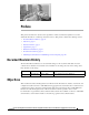
Chapter 9 Topology Hiding IPv6 Support Figure 9-1 illustrates a No NAPT media flow through the DBE between user side A and user side B. send No NAPT Media Flow 1 send recv 10.10.231.8:17002 2001:10::10/17002 82.19.12.134:28988 2001:11::11/28988 recv 4 User Side A 2 recv 10.10.231.8:17002 2001:10::10/17002 82.19.12.134:28988 2001:11::11/28988 recv send DBE 3 send User Side B 230526 Figure 9-1 1.
Chapter 9 Topology Hiding IPv6 Support Figure 9-2 illustrates a Single NAPT signaling flow through the DBE between user side A and user side B. Single NAPT Signaling Flow send 10.10.231.15:5060 2001:10::10/5060 recv User Side A 1 send recv 10.10.231.15:5060 2001:88::8/2028 4 10.10.231.15:5060 2001:10::10/5060 recv send 2 recv 82.19.12.134:5060 2001:11::11/5060 3 DBE send User Side B 230525 Figure 9-2 1.
Chapter 9 Topology Hiding No NAPT Pinholes Related Commands • The ipv6 address (session border controller) command sets or creates the IPv6 address prefix on an SBC interface. • The media-address ipv6 command adds an IPv6 address to the set of addresses that can be used by the DBE as a local media address. • The media-address pool ipv6 command creates a pool of sequential IPv6 media addresses that can be used by the DBE as local media addresses.
Chapter 9 Topology Hiding No NAPT Pinholes 9-10 • A hairpin of two pinholes in which both external terminations are provisioned with the NAT latching instruction cannot latch and cannot forward media. No NAPT pinholes are not allowed to (re)latch to the remote addresses on both sides. • IPv6 hairpinning are supported on UDP and TCP. • Coupling of Single NAPT pinholes is not supported.
CH A P T E R 10 High Availability Support This chapter describes high availability support for the Integrated Session Border Controller (SBC) on the Cisco ASR 1000 Series Aggregation Services Routers.
Chapter 10 High Availability Support Hardware Redundancy Hardware Redundancy Integrated Session Border Controller supports use of a redundant or standby Route Processor (RP) and redundant Embedded Services Processor (ESP) on the Cisco ASR 1006 Router. The Cisco ASR 1006 Router has an ESP as well as an RP for dual hardware redundancy. If the active RP or active ESP hardware fails, the system performs a switchover to the standby RP or standby ESP. RP and ESP hardware redundancy support is independent.
Chapter 10 High Availability Support SSO Support Upon an RPR-based RP switchover event, all SBC calls already established (in a steady state) at the time of the switchover are lost. Some SBC calls in the process of being established at the time of the switchover are dropped as gracefully as possible. No new calls can be established briefly after the initial switchover event.
Chapter 10 High Availability Support ISSU Support 10-4 Cisco IOS XE Integrated Session Border Controller Configuration Guide for the Cisco ASR 1000 Series Aggregation Services Routers OL-15421-01
CH A P T E R 11 Quality Monitoring and Statistics Gathering The Data Border Element (DBE) deployment of the Integrated Session Border Controller (SBC) has a main objective in supporting quality monitoring and statistics reporting. The DBE supports generation of event messages detailing significant events that occur on each call. In addition, the DBE supports generation of correct billing, call usage and detail records.
Chapter 11 Quality Monitoring and Statistics Gathering Billing and Call Detail Records Billing and Call Detail Records One main function of SBC is to generate correct billing, call detail and usage records. The DBE supports collecting statistics data and sending the data to the Signaling Border Element (SBE).
Chapter 11 Quality Monitoring and Statistics Gathering Enhanced Event Notification and Auditing • If the DBE switched to a new MGC for some reason, the new MGC had no means to learn what events had occurred on the streams and terminations programmed on the DBE.
Chapter 11 Quality Monitoring and Statistics Gathering Enhanced Event Notification and Auditing Association Reset A configuration option (the h248-association-timeout command) has been added that allows an alternative association reset behavior. The possible options are: • The it/ito event is the only event where failure to notify the SBE about it causes the H.248 association with the SBE to be reset. (This behavior is the default and the standard H.248 protocol behavior.
Chapter 11 Quality Monitoring and Statistics Gathering H.248 Network Package Quality Alert Event and Middlebox Pinhole Timer Expired Event H.248 Network Package Quality Alert Event and Middlebox Pinhole Timer Expired Event When the DBE detects media loss (media has stopped flowing and a call is not on hold), the DBE may issue one or more H.248/Megaco events to the media gateway controller (MGC): a Network (nt) package Quality Alert (qualert) event, a Middlebox Pinhole Timer Expired event1, or both events.
Chapter 11 Quality Monitoring and Statistics Gathering Provisioned Inactivity Timer Related Command The h248-media-alert-event command is used to enable or disable the Middlebox Pinhole Timer Expired event when the DBE detects media loss. Provisioned Inactivity Timer The DBE can be configured with a default value for the H.248 connection’s inactivity timer value (the it and ito properties).
INDEX command syntax A conventions active RP 10-2 adr package i-xii configuring 8-2 Cisco H.248 profile architecture 2-14 controller, individual deployment scenario SBC example 1-8 controllers, global 2-13 2-11 1-2 DBE ASR 1002 Router 10-1 detailed steps ASR 1004 Router 10-1 DTMF ASR 1006 Router 10-1 H.
Index differentiated services code point diffserv package distributed model DSCP 1-2, 1-8 10-3 H.248 logging 2-6 H.248 Megaco 1-8 H.248 packages two-rate three-color policing and marking 5-5 11-4 6-1 address reporting package base root package 11-3 interworking 11-2 H.248 event subscription 11-2 5-3 DTMF 11-3, 11-4 H.248 event notification 5-5 discarded packets statistics dropped calls H.248 association 5-3 6-2 6-7 enabling optional H.
Index twice NAPT pinholes hairpin support 5-5 mask length 7-5 hardware redundancy high availability 10-1 huge buffer size 2-1 8-4 maximum burst size 10-2 hiding network address hung call marking 7-5 mbs property 9-1 5-2 media address pools configuring example 11-2 4-2, 7-8 4-4, 7-9 prerequisites restrictions I media failure illustration media flow No NAPT 9-7 inactivity timer 10-3 interim authentication header inter-subscriber blocking ipv4 8-3 9-2 media loss media packe
Index DBE status notification 11-2 enhanced event notification H.
Index SDP 5-2 T sdr property 5-2 security, SBC termination name hierarchy 8-1 firewall termination state control 8-2 H.248 address reporting package 8-4 8-5 traffic management policing Tman package i-xiii 5-1 t-max timer 7-14 token bucket 5-6 two-rate three-color policing and marking 8-5, 8-6, 9-1 traffic management, H.
Index video on demand systems 7-14 VLAN package syntax-level support VoD support 7-14 voice over IP 1-1 voice tones 6-6 3-1 W wildcarding support IN-6 7-3 Cisco IOS XE Integrated Session Border Controller Configuration Guide for the Cisco ASR 1000 Series Aggregation Services Routers OL-15421-01