
Network Card User Manual


Installing the Cisco AS5800 3-21
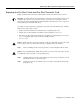
Connecting the AC Power Cables
Caution Do not plug the AC-input power shelf into the same power source as the router shelf or
into the power strip on your equipment rack. The 20A connectors on the AC-input power shelf are
incompatible with the power source used for the router shelf and with the 15A power strips used in
most equipment racks.
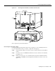
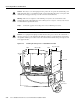
Figure 3-16 Connecting the AC Power Cords to a Standard Power Shelf
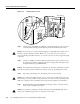
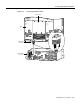
Figure 3-17 Connecting the AC Power Cords to an Enhanced Power Shelf
This completes the AC power cord installation.
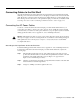
Installing the Safety Cover on the Standard Power Shelf
For safety reasons, you must install the metal safety cover that shipped with your standard AC-input
power shelf before you power up the system. The safety cover shields the power connections from
possible short circuit and protects you from electrical shock.
Note This is not necessary with the enhanced power supply.
To install the safety cover, follow these steps:
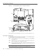
Step 1 Align the metal safety cover with the grooves on the back underside of the dial shelf. (See
Figure 3-18.)
Step 2 Slide the safety cover into place and attach the front of the cover to the dial shelf with the
screws provided.
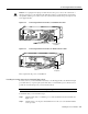
H11154
BUS
—
BUS
+
AC-input power
receptacles
AC power cable
24517
AC power cable
AC-input power
receptacles