
Network Card User Manual
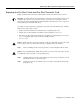


Connecting Cables to the Dial Shelf
Cisco AS5800 Universal Access Server Hardware Installation Guide3-20
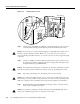
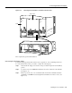
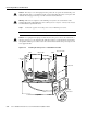
Figure 3-15 Connecting the Monitor Cable to an Enhanced Power Shelf
This completes the monitor cable installation. You must now connect the AC-input power cords.
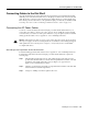
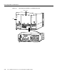
Connecting the AC Power Cords
For detailed cabling specification information, refer to Appendix A, “Cisco AS5800 Specifications.”
To connect the AC power cords, complete the following steps:
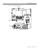
Step 1 Feed the rectangular ends of the AC power cords through the spaces in the DC PEMs as
shown in Figure 3-18.
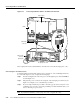
Step 2 Plug each AC power cord into an AC receptacle on the AC-input power shelf rear. (See
Figure 3-16, or Figure 3-17 for an enhanced power shelf.)
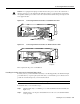
Step 3 If you are using an enhanced power shelf, connect the opposite end of each power cord to
a 220VAC power source. If you are using a standard power shelf, install the safety cover
before connecting to a power source.
Note For maximum redundancy, connect each power cord to a separate AC source.
–
4
8
V
–
4
8
V
R
T
N
C
N
C
N
O
P
O
W
E
R
M
I
S
W
I
R
E
C
N
C
N
O
P
O
W
E
R
M
IS
W
IR
E
–
4
8
V
–
4
8
V
R
T
N
24601
DB-9 cable
connector
DB-25 cable
connector
(alarm port)
PEM
Filter module
AC-input power shelf