
Network Card User Manual


Connecting Cables to the Dial Shelf
Cisco AS5800 Universal Access Server Hardware Installation Guide3-18
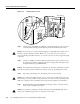
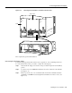
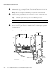
Figure 3-13 Connecting the DC-Interconnect Cables
Step 4
Fit the exposed wire end of the black insulated cable into the DC terminal block labeled
–48V on each PEM and securely tighten the terminal block connector screws. Repeat for
the other PEM. (See Figure 3-13)
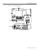
Note You must attach the red DC cables to the stud labeled BUS + on the AC-input power shelf and
connect the other end to a –48V RTN terminal on each PEM. You must attach the black DC cables
to the stud labeled BUS – and connect the other end to a –48V terminal on each PEM. If the two DC
conductors entering the PEM terminal block are reversed, a yellow warning LED on the PEM lights
to indicate a miswire. No damage will occur; however, you must power OFF the power at the source
and reverse the connections.
This completes the DC power cabling installation. You must now connect the monitor cable from the
AC-input power shelf to the dial shelf filter module.
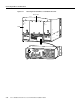
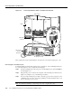
Connecting the Monitor Cable
For detailed cabling specification information, refer to Appendix A, “Cisco AS5800 Specifications.”
To connect the monitor cable, complete the following steps:
Step 1 Attach the monitor cable DB-9 plug to the DB-9 receptacle at the base of the dial shelf
filter module. (See Figure 3-14, or Figure 3-14 for an enhanced power shelf.)
Step 2 Tighten the jackscrews.
Hex nut
Red
Black
Ground
–
4
8
V
–
4
8
V
R
T
N
C
N
C
N
O
C
N
C
N
O
–
4
8
V –
4
8
V
R
T
N
H11158
–48V
–48V
RTN
DC terminal block
PEM
BUS
—
terminal
stud
BUS
+
terminal
stud
Red
Black
Monitor
cable