
Network Card User Manual


Replacing the Dial Shelf Components
Cisco AS5800 Universal Access Server Hardware Installation Guide3-14
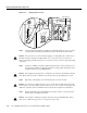
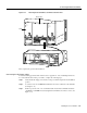
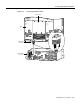
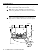
Figure 3-10 Using the Ejector Levers
Step 4
Seat the card in the backplane by pushing the card firmly until the ejector levers fold in
toward the trunk card front panel and the front panel is flush with the chassis frame.
Caution Always use the ejector levers when disengaging or seating trunk cards, modem cards, or
dial shelf controller cards in the dial shelf. Failure to do so can cause erroneous system error
messages indicating a card failure. However, do not use the ejector levers to lift or support the weight
of the cards.
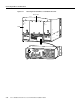
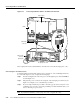
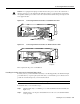
Step 5 Using a No. 2 Phillips screwdriver, tighten the panel fasteners on the top and bottom of
the card front panel. This prevents the card from becoming partially dislodged from the
backplane and ensures proper EMI shielding.
Caution Always tighten the panel fasteners on trunk cards, modem cards, and dial shelf controller
cards. These fasteners prevent accidental removal and provide proper grounding for the system.
Step 6 Repeat Step 3 through Step 5 for all remaining cards you want to install.
Caution To avoid erroneous failure messages, remove or insert only one trunk card at a time. Also,
after inserting or removing a trunk card, allow at least 15 sec. before removing or inserting another
trunk card so that the system can reinitialize and note the current configuration of all interfaces.
Step 7 Install a blank filler card (DS58-BLANK=) in all empty card slots to keep the chassis
dust-free and to maintain proper airflow.
Caution To prevent the overheating of internal components, always install blank filler cards in
empty slots to maintain the proper flow of cooling air across the cards.
PWR
E1FR
HCPU
MAINT
T1FR
FCPU
RALM
LALM
MONITOR#
NLOOP
75
PWR
E1FR
HCPU
MAINT
T1FR
FCPU
RALM
LALM
0
MONITOR#
NLOOP
75
PWR
HCPU
CALLS
MAINT
MODEMS
H11097
PWR
E1FR
HCPU
MAINT
T1FR
FCPU
PWR
E1FR
HCPU
MAINT
T1FR
FCPU
Panel fastener