
Network Card User Manual

Replacing the Dial Shelf Components
Cisco AS5800 Universal Access Server Hardware Installation Guide3-12
Replacing the Power-Entry Modules
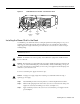
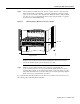
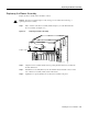
To reinstall the PEMs, complete the following steps. (Refer to Figure 3-9 to locate the PEMs in the
dial shelf.)
Step 1 Grasp the PEM handle and carefully align the PEM with the DC-input power supply bay.
Step 2 Slide the PEM into the power supply bay until it is fully seated and connected to the
backplane connectors.
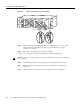
Step 3 Using a 1/4-inch flat-blade screwdriver, tighten the captive screws on the PEM front
panel.
Step 4 Plug the alarm cables into the bell alarm terminal block. (See Figure 3-9.)
Step 5 Repeat Step 1 to Step 4 for the other PEM.
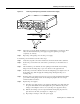
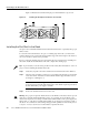
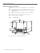
Figure 3-9 Replacing a PEM
This completes the procedure for replacing a PEM in the dial shelf.
LEDs
–
4
8
V
–
4
8
V
R
T
N
C
N
C
N
O
P
O
W
E
R
M
IS
W
IR
E
C
N
C
N
O
P
O
W
E
R
M
IS
W
IR
E
–
4
8
V
–
4
8
V
R
T
N
H11077
DC-input power
terminal block
Captive
screw
Captive
screw
Bell alarm
terminal block
Filter module
PEM