
Network Card User Manual

Installing the Cisco AS5800 3-11
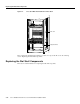
Replacing the Blower Assembly
Replacing the Blower Assembly
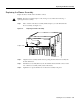
Replace the blower module in the dial shelf as follows:
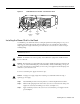
Caution The blower assembly weighs 27.5 lb (12.5 kg). Use two hands when removing or
replacing the blower assembly.
Step 1 Place one hand on the blower assembly handle and place your other hand under the
blower assembly. (See Figure 3-8.)
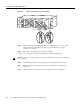
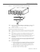
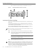
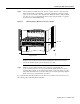
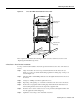
Figure 3-8 Replacing the Blower Assembly
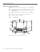
Step 2
Align the blower assembly with the chassis opening and slide the blower assembly into
the dial shelf chassis.
Step 3 Push the blower assembly all the way into the dial shelf chassis until the connector on the
rear of the blower assembly is fully seated in the chassis.
Step 4 Tighten the two captive thumbscrews on the blower assembly front panel.
PWR
E1FR
HCPU
MAINT
T1FR
FCPU
RALM
LALM
0
MONITOR#
NLOOP
75
1
2
PWR
E1FR
HCPU
MAINT
T1FR
FCPU
RALM
LALM
0
MONITOR#
NLOOP
75
1
2
PWR
HCPU
CALLS
MAINT
MODEMS
PWR
HCPU
CALLS
MAINT
MODEMS
PWR
HCPU
CALLS
MAINT
MODEMS
PWR
HCPU
CALLS
MAINT
MODEMS
PWR
HCPU
CALLS
MAINT
MODEMS
PWR
HCPU
CALLS
MAINT
MODEMS
PWR
HCPU
CALLS
MAINT
MODEMS
PWR
HCPU
CALLS
MAINT
MODEMS
PWR
HCPU
CALLS
MAINT
MODEMS
PWR
HCPU
CALLS
MAINT
MODEMS
PWR
MIN
MAJ
ACO
CUTOFF
MBUS
HIST
ALARM
ALARM
DISP
CLEAR
SET
CLK
SLOT 0
SLOT 1
MAST
DISP
PCMCIA
DIAL
ATTEN
PWR
MIN
MAJ
ACO
CUTOFF
MBUS
HIST
ALARM
ALARM
DISP
CLEAR
SET
CLK
SLOT 0
SLOT 1
MAST
DISP
PCMCIA
DIA
ATTEN
P
O
W
E
R
F
A
I
L
H10999
Captive screws