
Network Card User Manual

Installing the Cisco AS5800 3-9
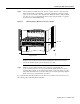
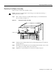
Mounting the Rear Brackets
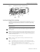
Figure 3-6 Cisco 5814 Dial Shelf Installed in a Telco Rack
This completes the dial shelf rack-mounting procedures for a telco rack. Proceed to the section
“Replacing the Dial Shelf Components.”
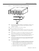
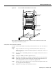
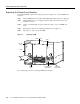
4-Post Rack—Rear Bracket Installation
For a 4-post rack-mount installation, mount the optional rear brackets to the sides of the chassis as
follows:
Step 1 Align one bracket to the lower rear position threaded holes in the chassis side (see
Figure 2-7, position d), with the bracket flange against the mounting strip or rack post, as
shown in Figure 3-6.
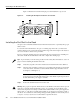
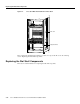
Step 2 Thread two M5 x 10-mm Phillips flathead screws through the bracket and into the side of
the chassis.
Step 3 Using a No. 2 Phillips screwdriver, tighten the screws.
Step 4 Repeat Step 1 through Step 3 to mount the rear bracket on the other side of the chassis.
Step 5 Position the rear equipment rack-mounting strips flush with the dial shelf chassis rear
rack-mounting brackets and secure the strips in the equipment rack.
Step 6 Insert the 10-32 x 3/8-in. slotted screws (2 screws per bracket) through the brackets and
into the equipment rack-mounting strip.
Step 7 Tighten the screws using a 1/4-in. flat-blade screwdriver.
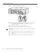
Center lower
bracket (c)
H11597
Forward lower
bracket (b)
Support brackets
Forward upper
bracket (a)