
Network Card User Manual

Connecting to an AC Power Source
Cisco AS5800 Universal Access Server Hardware Installation Guide3-2
This section explains how to attach the power cables and rack-mount the AC-input power shelf. For
detailed cabling specification tables, refer to Appendix A, “Cisco AS5800 Specifications.”
Parts Required
You need the following tools and parts to rack-mount the power shelf:
• AC-input power shelf or enhanced AC-input power shelf with dual AC power supplies
• Two AC power cables
• Two pairs of DC interconnect cables (CAB-5800-ACDC=)
• One DB-25 to DB-9 monitor cable (CAB-PEM=)
• One 6 gauge ground cable
• Two hex nuts and M4 screws
• Four 10-32 x 3/8-in. slotted screws
• One metal safety cover and screws
• 3/8-in. nut driver
• No. 2 Phillips screwdriver
• 1/4-in. flat-blade screwdriver
• Wire strippers, if needed, for your DC power cables
• Several cable ties to temporarily anchor the cables out of the way, if necessary
To connect the power cables and power up the system, proceed to the following section “Connecting
the AC Power Cables.”
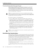
Mount the Cables on the AC Power Supply
It is possible to mount the cables on the AC power supply after it has been rack-mounted, but given
the limited space in and around many equipment racks, we recommend that you mount the cables
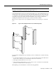
before rack-mounting the AC power supply. Figure 3-1 shows cables mounted on a standard AC
power supply, but the process is the same for the enhanced power supply. For a picture of the rear of
the enhanced power supply, see Figure 1-17. To mount the AC power supply cables:
Step 1 Attach the ground-cable double ring lug to the ground posts on the rear of the AC-input
power shelf. (See Figure 3-1, lower chassis.)
Step 2 Secure the double ring lug to both threaded ground posts with a hex nut on each stud.
Step 3 Attach two red DC-interconnect power-cable ring lugs to the terminal stud labeled BUS +
on the AC power shelf chassis rear. (See Figure 3-1.)
Step 4 Secure the ring lugs to the threaded stud with a hex nut.
Step 5 Attach two black DC-interconnect power-cable ring lugs to the terminal stud labeled
BUS – on the AC power shelf chassis rear. (Refer to Figure 3-1.)
Step 6 Secure the ring lugs to the threaded terminal stud with a hex nut.
Step 7 Attach the monitor cable DB-25 plug to the DB-25 receptacle on the rear of the AC-input
power shelf. (See Figure 3-1.) Tighten the jackscrews.