
Network Card User Manual

CHAPTER
Installing the Cisco AS5800 3-1
3
Installing the Cisco AS5800
This chapter explains the procedures for installing the access server. Installation involves the
following tasks:
1 Connecting cables to the AC power supply (AC installs only)
1 Rack-mounting the AC power supply (AC installs only)
2 Rack-mounting the dial shelf
3 Replacing the blower assembly, DC PEMs, and dial shelf cards or controller cards
4 Connecting power inputs to the DC PEMs
5 Mounting the AC power safety cover (AC installs only)
6 Rack-mounting the router shelf
7 Connecting all remaining cable connections
Estimated time to install the access server hardware is between 2 and 3 hours.
Note If you are installing the optional AC-input power shelf, refer to the“Connecting to an AC
Power Source” section on page 3-1.
This chapter assumes that you are installing the access server manually. If you have access to a
forklift or hydraulic equipment during the installation, you can omit certain steps, which are
specified later in this chapter.
Connecting to an AC Power Source
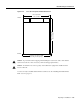
If your site has access to an AC power source only, you need to install the optional AC-input power
shelf (DS58-PWR-2AC) to convert to DC-input power for the dial shelf.
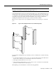
AC-input power is accepted using a separate, self-contained AC-input power shelf, which converts
AC-input power to DC-output for use by the DC-powered dial shelf. The AC-input is supplied by
two AC power cables (CAB-DS-AC=, other options available), converted to –48V DC-output power
for the dial shelf PEMs using two AC-to-DC power cables (DS5800-CAB-ACDC=) supplied by
Cisco.
The AC-input power shelf is an optional component of the Cisco AS5800 and is used to convert
AC-input power into DC-output power for the DC-powered Cisco 5814 dial shelf. The AC-input
power shelf contains two AC-input power supplies.