
Network Card User Manual

Preparing for Installation 2-17
Rack-Mounting Considerations
Note One rack unit (1.75 in. or 4.4 cm) is the maximum distance between the dial shelf and the
AC-input power shelf that accommodates the required safety cover.
Some equipment racks provide a power strip along the length of one of the mounting strips. If your
rack has a power strip, consider the position of the strip when planning fastener points to ensure that
you will be able to slide dial shelf cards and dial shelf controller cards straight out of their respective
slots. If the power strip does impair a rack-mount installation, remove the power strip before
installing the dial shelf in the rack, then replace it after the dial shelf is installed.
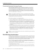
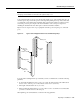
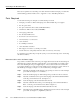
Figure 2-9 shows a typical 19-in. 4-post equipment rack with a power strip along one of the back
posts.
Figure 2-9 Typical 19-Inch Equipment Rack Posts and Mounting Strips
To use the rack-mounting hardware provided with your Cisco 5814 dial shelf, consider the following
guidelines:
• To mount the dial shelf between two 19-in. posts or rails, the inner clearance (the width between
the inner sides of the two posts or rails) must be at least 17.5 in. (44.45 cm).
• The height of the dial shelf is 28 in. (71.12 cm).
• When mounting the dial shelf in 4-post or telco racks, be sure to use all the screws and brackets
provided to secure the chassis to the rack posts.
When planning your rack installation, consider the following guidelines:
18.31 in.
(46.48 cm)
hole
center-to-center
17.5 in.
(44.45 cm)
min.
Rack posts
Mounting strips
110 VAC
outlets
10327