
Network Card User Manual

Preparing for Installation 2-11
Installing the Rack-Mount Brackets on the Chassis
Installing the Rack-Mount Brackets on the Chassis
Bracket placement depends on the type of rack you use to install your access server. This section
describes both a 4-post rack installation and a telco rack installation.
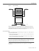
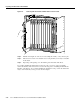
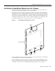
Threaded holes on the chassis sides are strategically located to position and mount bracket hardware.
The dial shelf also has a mounting flange in front for flush-front mounting. If you are mounting the
dial shelf in a 4-post rack, you have the option of using two brackets (one on each side) placed toward
the lower rear of the chassis (see Figure 2-7, position d) to support the chassis in the back. If you are
mounting the dial shelf in a telco rack, you need to offset the dial shelf 5 in. beyond the rack center
post and use six brackets (three on each side) at positions a, b, and c (See Figure 2-7).
Figure 2-7 Dial Shelf Bracket Mounting Hole Positions
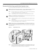
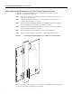
If you are installing your access server in a telco rack, proceed to the following section, “Mounting
Forward Brackets for an Offset Telco Rack Installation.”
If you are installing your access server in a 4-post rack, you do not need to install brackets on the
chassis front; use the permanent metal flanges on the chassis front to install the dial shelf in the rack.
(See Figure 2-7.) Proceed to the ““Installing the Dial Shelf in the Rack” section on page 3-6.
Rear
lower
H11047
Front
Rear
Forward
upper
Mounting flange
Forward
lower
Center
lower
a
b
c
d