
Network Card User Manual

Preparing the Dial Shelf for Rack-Mount
Cisco AS5800 Universal Access Server Hardware Installation Guide2-10
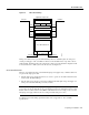
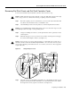
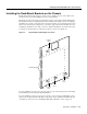
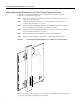
Figure 2-6 Removing Dial Shelf Cards and Dial Shelf Controller Cards
Step 6
Pull the card straight out of the slot. Avoid touching the circuitry or any connector pins.
Step 7 Place the removed card on an antistatic mat or foam pad until you are ready to reinstall it
in the chassis.
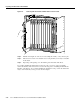
Step 8 Repeat Step 3 through Step 7 for all remaining cards in the dial shelf chassis.
If you will be installing the dial shelf in an offset telco rack, you are now ready to install the
rack-mount brackets on the chassis. Proceed to the following section, “Installing the Rack-Mount
Brackets on the Chassis.” If you will be installing the dial shelf in a four post rack, the dial shelf is
ready to rack mount and you may proceed to the next chapter.
RMON
TMON
PWR
E1FR
HCPU
MAINT
T1FR
FCPU
CHANNELIZED E1/T1
RALM
LALM
0
MONITOR#
NLOOP
75
1
2
3
4
5
6
7
8
9
10
11
CHANNELIZED E1/T1
MAINT
MONITOR #
LALM
RALM
T1FR
FCPU
PWR
E1FR
HCPU
75
NLOOP
0
1
2
3
4
5
6
7
8
9
10
11
RMON
TMON
MODEM
PWR
HCPU
CALLS
MAINT
MODEMS
MODEM
PWR
HCPU
CALLS
MAINT
MODEMS
MODEM
PWR
HCPU
CALLS
MAINT
MODEMS
MODEM
PWR
HCPU
CALLS
MAINT
MODEMS
MODEM
PWR
HCPU
CALLS
MAINT
MODEMS
MODEM
PWR
HCPU
CALLS
MAINT
MODEMS
MODEM
PWR
HCPU
CALLS
MAINT
MODEMS
MODEM
PWR
HCPU
CALLS
MAINT
MODEMS
MODEM
PWR
HCPU
CALLS
MAINT
MODEMS
MODEM
PWR
HCPU
CALLS
MAINT
MODEMS
PWR
MIN
MAJ
ACO
CUTOFF
DIAL SHELF INTERCONNECT
MBUS
HIST
ALARM
ALARM
DISP
CLEAR
SET
CLK
SLOT 0
SLOT 1
MAST
DISP
PCMCIA
CONSOLE NETWORK CLOCK ALARMS 10 BASE T
DSI
DIAL SHELF CONTROLLER
ATTEN
PWR
MIN
MAJ
ACO
CUTOFF
DIAL SHELF INTERCONNECT
MBUS
HIST
ALARM
ALARM
DISP
CLEAR
SET
CLK
SLOT 0
SLOT 1
MAST
DISP
PCMCIA
CONSOLE NETWORK CLOCK ALARMS 10 BASE T
DSI
DIAL SHELF CONTROLLER
ATTEN
H11040