
Network Card User Manual
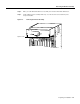

Preparing the Dial Shelf for Rack-Mount
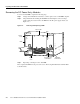
Cisco AS5800 Universal Access Server Hardware Installation Guide2-8
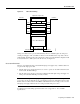
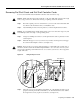
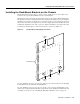
Removing the DC Power-Entry Modules
To remove the DC PEMs, complete the following steps:
Step 1 Using a 1/4-inch flat-blade screwdriver, loosen the captive screws on the PEM front panel.
Step 2 Grasp the handle and carefully pull the PEM from the backplane connectors using a
gentle rocking motion; then remove the PEM from the DC power supply chassis. (See
Figure 2-4.)
Figure 2-4 Removing and Replacing a PEM
Step 3
Repeat Step 1 and Step 2 for the other PEM.
This completes the PEM removal process. Proceed to “Removing Dial Shelf Cards and Dial Shelf
Controller Cards.”
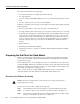
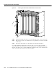
LEDs
–
4
8
V
–
4
8
V
R
T
N
C
N
C
N
O
P
O
W
E
R
M
IS
W
IR
E
C
N
C
N
O
P
O
W
E
R
M
IS
W
IR
E
–
4
8
V
–
4
8
V
R
T
N
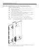
H11077
DC-input power
terminal block
Captive
screw
Captive
screw
Bell alarm
terminal block
Filter module
PEM