
Network Card User Manual

Preparing for Installation 2-7
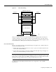
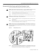
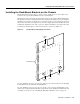
Removing the Blower Assembly
Step 4 Place your other hand under the blower assembly as it extends from the dial shelf chassis.
Step 5 Slowly pull the blower assembly all the way out of the slot and set it aside until you are
ready to reinstall it.
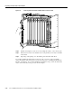
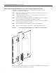
Figure 2-3 Removing the Blower Assembly
PWR
E1FR
HCPU
MAINT
T1FR
FCPU
RALM
LALM
0
MONITOR#
NLOOP
75
1
2
PWR
E1FR
HCPU
MAINT
T1FR
FCPU
RALM
LALM
0
MONITOR#
NLOOP
75
1
2
PWR
HCPU
CALLS
MAINT
MODEMS
PWR
HCPU
CALLS
MAINT
MODEMS
PWR
HCPU
CALLS
MAINT
MODEMS
PWR
HCPU
CALLS
MAINT
MODEMS
PWR
HCPU
CALLS
MAINT
MODEMS
PWR
HCPU
CALLS
MAINT
MODEMS
PWR
HCPU
CALLS
MAINT
MODEMS
PWR
HCPU
CALLS
MAINT
MODEMS
PWR
HCPU
CALLS
MAINT
MODEMS
PWR
HCPU
CALLS
MAINT
MODEMS
PWR
MIN
MAJ
ACO
CUTOFF
MBUS
HIST
ALARM
ALARM
DISP
CLEAR
SET
CLK
SLOT 0
SLOT 1
MAST
DISP
PCMCIA
DIAL
ATTEN
PWR
MIN
MAJ
ACO
CUTOFF
MBUS
HIST
ALARM
ALARM
DISP
CLEAR
SET
CLK
SLOT 0
SLOT 1
MAST
DISP
PCMCIA
DIA
ATTEN
P
O
W
E
R
F
A
I
L
H10999
Captive screws