
Network Card User Manual
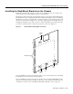

Preparing the Dial Shelf for Rack-Mount
Cisco AS5800 Universal Access Server Hardware Installation Guide2-6
The rack-mount kit includes the following parts:
• Six rack-mount brackets for mounting the dial shelf in the rack
• Two support brackets
• A total of 12 M5 x 10-mm Phillips flathead screws to secure the rack-mount brackets to the dial
shelf
• A total of 16 slotted 10-32 x 3/8 screws for rack installation
In addition, you might need the following external equipment, especially when installing a split dial
shelf configuration:
• Data service unit (DSU) to connect each serial port to an external network
• A serial port adapter cable for each serial port to connect the port with a remote device or network
• T1 channel service unit/data service unit (CSU/DSU) that converts the HDLC synchronous serial
data stream into a T1 data stream with the correct framing and ones density to connect. Some
telephone systems require a minimum number of 1 bit per time unit in a data stream, called ones
density, to connect a serial port to a T1 network. Several T1 CSU/DSU devices are available as
additional equipment, and most provide either a V.35, EIA/TIA-449, or EIA-530 electrical
interface.
• Ethernet transceiver
• Token Ring media attachment unit (MAU)
• Optical bypass switch or concentrator for multimode Fiber Distributed Data Interface (FDDI)
connections
Preparing the Dial Shelf for Rack-Mount
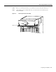
The Cisco 5814 dial shelf is shipped with the blower assembly and all dial shelf cards (trunk and
modem cards) and dial shelf controller cards installed in the chassis. Fully loaded, the dial shelf
weighs 278 lb (126.1 kg).
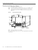
Before installing the Cisco 5814 in an equipment rack, we recommend that you remove the blower
assembly, DC PEMs, dial shelf cards, and dial shelf controller cards from the dial shelf, then reinstall
them after the dial shelf is mounted in the rack. (If you are using a forklift or other machinery to lift
the dial shelf, you might want to omit this process.)
After you remove the blower assembly, PEMs, and the installed cards, you will mount the
rack-mount brackets on the dial shelf chassis and install the dial shelf in the rack.
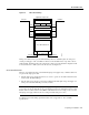
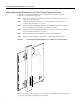
Removing the Blower Assembly
Caution The blower assembly weighs 27.5 lb (12.5 kg). Use two hands when removing or
replacing the blower assembly.
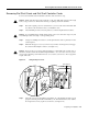
To remove the blower assembly, complete the following steps:
Step 1 Attach an ESD-preventive wrist strap between you and an unpainted chassis surface.
Step 2 Loosen the two captive screws on the blower assembly front panel. (See Figure 2-3.)
Step 3 Grasp the blower assembly handle with one hand and pull the blower assembly straight
toward you, about halfway out of the slot. (See Figure 2-3.)