
Network Card User Manual

Online Insertion and Removal
Cisco AS5800 Universal Access Server Hardware Installation Guide1-44
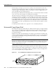
Each DSC card and dial shelf card contains female connectors that connect to the system backplane.
Each male backplane connector comprises a set of tiered pins in three lengths. The backplane pins
send specific signals to the system as they make contact with the card connectors. The system
assesses the signals it receives and the order in which it receives them to determine whether to
initialize a startup or shutdown procedure.
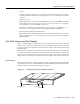
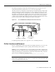
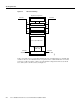
Each DSC card and dial shelf card is designed with two ejector levers to be used when you install or
remove a card. The function of the ejector levers (see Figure 2-5) is to align and securely seat the
card connectors in the backplane and facilitate the installation and removal process.
Do not force the DSC cards or dial shelf cards into the slot, because this can damage the card
connector pins if they are not aligned properly with the card connectors.
To avoid erroneous failure messages, you must allow at least 15 sec for the system to reinitialize and
note current interface configurations before you remove or insert another DSC card or dial shelf card
in the dial shelf.