
Network Card User Manual

Power Requirements
Cisco AS5800 Universal Access Server Hardware Installation Guide1-42
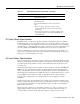
Each AC-input power supply is powered on by a separate power switch, which is located on the
AC-input power shelf front panel. (See Figure 1-23.) Ejector levers with locking spring clips secure
each power supply to the backplane connectors, and a handle on each power supply allows you to
remove and replace the power supplies with ease.
The AC-input power shelf is three rack-units high (5.25 in. [13.3 cm]) and rack-mounts in a standard
19-in., 4-post or telco rack assembly, one rack unit below the dial shelf.
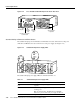
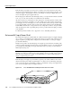
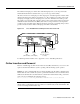
All cable connections for AC-input power, DC-output power, and status signals are made from the
AC-input power shelf rear. (See Figure 1-24.) Two modular power cables connect each AC-input
power supply to the site’s AC-input power source. Two DC-interconnect cables provide DC-output
power to the dial shelf. A monitor cable provides a status signal connection to the dial shelf filter
module MBus, which monitors voltage tolerance levels, temperature conditions, and power failure
in the AC-input power shelf. A grounding cable provides a ground from the AC-input power shelf
to the dial shelf.
For detailed specification tables, refer to Appendix A, “Cisco AS5800 Specifications.”
Enhanced AC-Input Power Shelf
The enhanced AC-input power shelf includes two 2,000-watt (W) AC-input power supplies that plug
into a common power backplane in the enhanced AC-input power shelf. A single AC-input power
supply is capable of powering a fully configured Cisco 5814 dial shelf. A second power supply
provides full redundancy.
During normal operation, the dual AC-input power supplies provide automatic load-sharing, with
each power supply supporting 50 percent of the power load. When you remove one of the AC-input
power supplies, the remaining power supply immediately ramps up to full power and maintains
uninterrupted system power.
Note The AC-input power supplies in the enhanced AC-input power shelf are “hot-swappable,”
allowing you to remove or replace a power supply while the system is operating; system operation
will not be affected. Whenever possible, we recommend that you connect each AC-input power
supply to a separate AC power source.
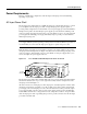
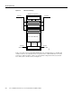
Each AC-input power supply is powered ON by a separate power switch, which is located on the
enhanced AC-input power shelf front panel (Figure 1-23). Ejector levers with locking spring clips
secure each power supply to the backplane connectors, and a handle on each power supply allows
you to remove and replace the power supplies with ease.
Figure 1-26 Cisco AS5800 Enhanced AC-Input Power Shelf—Front View
22150
AC GOOD
PWR FAIL
PWR GOOD
V OUT
+
-
AC GOOD
PWR FAIL
PWR GOOD
V OUT
+
-
A
C
P
O
W
E
R
A
A
C
P
O
W
E
R
B
Power
switches