
Network Card User Manual

Power Requirements
Cisco AS5800 Universal Access Server Hardware Installation Guide1-40
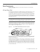
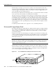
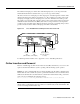
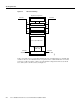
Figure 1-24 Cisco AS5800 Standard AC-Input Power Shelf—Rear View
Standard AC-Input Power Shelf LED Indicators
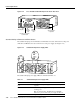
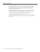
The standard AC-input power shelf includes two LEDs that are located on the left front of the power
shelf and four LEDs that are located on the front of each power supply. (See Figure 1-25.)
Figure 1-25 Standard AC-Input Power Supply LEDs
The standard AC-input power supply LEDs are summarized in Table 1-9.
Table 1-9 Standard AC-Input Power Supply LEDs
LED Color Description
AC POWER
1 & 2
Green Correspond to each power supply and are on when AC power
is present.
PWR OK Green On when the power supply is connected, powered on, and
receiving power.
Note For full redundancy, all PWR OK and AC POWER
LEDs on the power shelf and each power supply should be on.
FAULT Yellow Lights when the power shelf has detected an internal fault.
BUS
BUS
+
H11038
AC-input power
receptacles
Ground post
Ground post to BUS +
terminal stud
BUS
+
terminal
stud
BUS -
terminal
stud
H11155
A
C
1
P
O
W
E
R
2
C
B
2
P
W
R
O
K
F
A
U
L
T
T
E
M
P
I
L
I
M
P
W
R
O
K
F
A
U
L
T
T
E
M
P
I
L
I
M
C
B
1
PWR OK
FAULT
TEMP
I LIM
AC
1 POWER 2