
Network Card User Manual

Cisco AS5800 Product Overview 1-15
Dial Shelf Blower Assembly
Dial Shelf Blower Assembly
The blower assembly in the Cisco 5814 dial shelf monitors the dial shelf internal operating
temperatures and maintains acceptable cooling parameters. The blower assembly contains three
variable-speed impeller fans and a controller card that performs the following functions:
• Monitors internal temperatures
The controller card contains temperature sensors, which monitor internal air temperature within
the dial shelf chassis. These temperature sensors, along with other system maintenance sensors,
can detect areas exceeding the temperature set point.
• Controls fan operation
Fan speed is controlled by a microprocessor on the controller card. If air temperature within the
dial shelf chassis exceeds the acceptable operating range, the controller card increases the fan
speed in an attempt to control the temperature. If temperatures continue to rise, the controller card
linearly increases fan speed until the fans reach full speed. If acceptable operating temperatures
are still unobtainable, the system environmental monitor shuts down all internal power, thus
preventing equipment damage from excessive heat.
During normal operation, the three fans “load-share” to provide cooling. If one of the three fans
fails, a warning message displays on your console screen. The controller card then increases the
speed of the remaining operative fans to maintain acceptable temperature levels.
When all three fans are operating normally, fan speed is 1,600 rpm. As ambient air temperature
increases, fan speed increases accordingly. Thus, if one of the fans becomes inoperative, the
remaining fans increase fan speed to 2,400 rpm.
• Supports OIR
The blower assembly supports OIR, which means you can remove and replace the blower
assembly while the system is operating; system operation will not be affected. However, if you
expect the replacement process to exceed 1 min, we recommend that you shut down the system.
Normal blower assembly replacement is estimated not to exceed 30 sec.
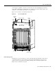
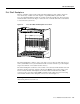
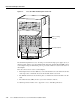
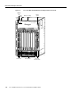
The blower assembly is located directly above the dial shelf cards and dial shelf controller cards in
the dial shelf. You install the blower assembly into the front of the dial shelf chassis where it plugs
directly into the dial shelf backplane. Figure 1-14 shows the location of the blower assembly in a
fully configured Cisco 5814 dial shelf, as viewed from the front of the system.
For detailed specification tables, refer to Appendix A, “Cisco AS5800 Specifications.”