
Network Card User Manual

Dial Shelf Field-Replaceable Units
Cisco AS5800 Universal Access Server Hardware Installation Guide1-14
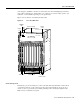
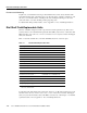
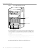
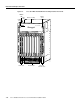
Figure 1-7 Cisco 5814 Dial Shelf Backplane—Rear View
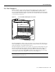
The dial shelf backplane first receives –48 VDC power from the DC-input power supplies by way of
the filter module, and the power is then distributed throughout the dial shelf. The DC PEMs connect
to the backplane using four blind-mating 1.25-in. power studs, which are located near the bottom of
the backplane.
Three bus connections are routed over the backplane:
• The backplane interconnect bus (BIC bus) connects the dial shelf cards to the dial shelf controller
cards and provides communication between the dial shelf and the router shelf.
• The TDM bus transmits clocks and frame pulses to all dial shelf cards and dial shelf controller
cards.
• The maintenance bus (MBus) monitors system environmental conditions.
For detailed specification tables, refer to Appendix A, “Cisco AS5800 Specifications.”
H11278
Blower assembly
connector
Dial shelf backplane
Power studs