
Network Card User Manual


Preparing to Repackage the Cisco 5814 Dial Shelf
Cisco 5814 Dial Shelf Packaging Replacement Instructions C-7
Step 9 Disconnect incoming CE1 or CT1 trunk line cables and secure them out of the way using
cable ties, if necessary. On the dial shelf controller card, disconnect the dial shelf
interconnect cable and the BNC connection if applicable.
This completes the power-off sequence. Proceed to the following section, “Preparing to Repackage
the Cisco 5814 Dial Shelf.”
Preparing to Repackage the Cisco 5814 Dial Shelf
The Cisco 5814 dial shelf is equipped with a blower assembly, dial shelf cards (trunk and modem
cards) and dial shelf controller cards configured in the chassis. Fully loaded, the dial shelf weighs
278 lb (126.1 kg).
Before removing the Cisco 5814 from the rack, we recommend that you remove the dial shelf cards,
dial shelf controller cards, and the blower assembly from the dial shelf to decrease the chassis weight
(see the “Removing the Blower Assembly” section on page 2-6 and the “Removing Dial Shelf Cards
and Dial Shelf Controller Cards” section on page 2-9), then reinstall the components (See the
“Replacing the Dial Shelf Components” section on page 3-10) after the dial shelf is seated on the
shipping pallet/base tray assembly.
Repackaging the Cisco 5814 Dial Shelf
To repackage the Cisco 5814 dial shelf, follow these steps:
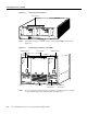
Step 1 Lay the opened plastic bag, with sides rolled down, on the pallet/base tray assembly. (See
Figure C-1.)
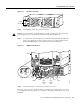
Step 2 Remove the screws securing the rear mounting brackets on the dial shelf to the rear rack
posts. Next, remove the rear brackets from the dial shelf chassis.
Caution If the dial shelf is suspended in the rack, install the two support brackets that were included
in your original rack-mount kit under the chassis to prevent it from falling while you are removing
the rack-mount screws and brackets.
Step 3 Remove the screws securing the front of the dial shelf chassis to the rack.
Step 4 Lift and slide the chassis out of the rack.
Warning Two people are required to lift the chassis. Use the handles on the chassis sides. To prevent
injury, keep your back straight and lift with your legs, not your back. To prevent damage to the
chassis and components, never attempt to lift the chassis with the handles on the power supplies, the
filter module, or on the blower assembly. These handles are not designed to support the weight of
the chassis. To see translations of the warnings that appear in this publication, refer to the Regulatory
Compliance and Safety Information document that accompanied this device.
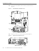
Step 5 Seat the dial shelf on the pallet/base tray assembly, and remove the front rack-mount
brackets from the chassis sides, if applicable.
Step 6 Place all accessories (including power cords, cables, documentation, and mounting
hardware) in the accessories box and tape the box closed.
Step 7 Replace the blower assembly, dial shelf cards, and dial shelf controller cards you removed
into the dial shelf chassis.