
Network Card User Manual


Cisco AS5800 Universal Access Server Hardware Installation Guide
Powering Off the Cisco AS5800
C-6
Step 7 Disconnect the monitor cable DB-9 connector from the base of the filter module. (See
Figure C-6.)
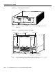
Figure C-6 Filter Module Monitor Cable DB-9 Connector
Step 8
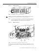
Disconnect power cables to the optional AC-input power shelf. (See Figure C-7.)
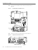
Figure C-7 AC-Input Power Shelf Cable Connections
.
–4
8V
–
4
8V
R
T
N
C
N
C
N
O
P
O
W
E
R
M
IS
W
IR
E
C
N
C
N
O
P
O
W
E
R
M
IS
W
IR
E
–
48
V
–
48
V
R
T
N
H11161
DB-9 cable
connector
DB-25 cable
connector
PEM
Filter module
AC-input power shelf
H11154
BUS
—
BUS
+
AC-input power
receptacles
AC power cable