
Network Card User Manual


Powering Off the Cisco AS5800
Cisco 5814 Dial Shelf Packaging Replacement Instructions C-5
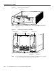
Figure C-4 AC-Input Power Shelf
Step 4
Power OFF the central office main circuit breaker.
Caution If you are using the optional AC-input power shelf, you must power off both AC-input
power supplies before you disconnect the DC cables from the DC terminal blocks.
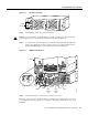
Step 5 Loosen the screws in the DC-input power terminal blocks and the alarm terminal blocks
using a 1/4-in. flat-blade screwdriver, and disconnect power cables and alarm cables to
the dial shelf PEMs. Figure C-5 shows the location of the terminal blocks.
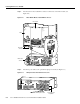
Figure C-5 PEM DC Terminal Block
Step 6
Disconnect the DC power cables from your DC power source.
The last two steps refer to the optional AC-input power shelf. If you are using a DC power source,
you can skip Step 7 and Step 8 and proceed to the section “Preparing to Repackage the Cisco 5814
Dial Shelf.”
H11098
A
C
1
P
O
W
E
R
2
C
B
2
P
W
R
O
K
F
A
U
L
T
T
E
M
P
I
L
IM
P
W
R
O
K
F
A
U
L
T
T
E
M
P
I
L
IM
C
B
1
Power
switches
Hex nut
Red
Black
Ground
–
4
8
V
–
4
8
V
R
T
N
C
N
C
N
O
C
N
C
N
O
–
4
8
V –
4
8
V
R
T
N
H11158
–48V
–48V
RTN
DC terminal block
PEM
BUS
—
terminal
stud
BUS
+
terminal
stud
Red
Black
Monitor
cable