
Network Card User Manual


Cisco AS5800 Universal Access Server Hardware Installation Guide
Powering Off the Cisco AS5800
C-4
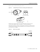
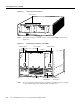
Figure C-2 Router Shelf Power Switches
Step 2
Power OFF (O) the power switches located on each dial shelf PEM front panel. (See
Figure C-3.)
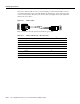
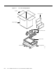
Figure C-3 Dial Shelf Power Switches on the PEMS
Step 3
If you are using the optional AC-input power shelf, power OFF (O) the power switches
located on the AC-input power shelf front panel. (See Figure C-4.)
H11572
N
E
T
W
O
R
K
P
R
O
C
E
S
S
I
N
G
E
N
G
IN
E
-
1
5
0
Power switches
H11655
–
4
8
V
–
4
8
V
R
T
N
C
N
C
N
O
P
O
W
E
R
M
IS
W
IR
E
C
N
C
N
O
P
O
W
E
R
M
IS
W
IR
E
–
4
8
V
–
4
8
V
R
T
N
Power switches
LEDs
DC-input power
terminal block
Bell alarm
terminal block
Filter module
PEM front panel
PEM front panel